Infiniti G35 (V35) Sedan. Manual - part 777
HAC-80
< COMPONENT DIAGNOSIS >
[AUTOMATIC AIR CONDITIONER]
INTAKE DOOR MOTOR
INTAKE DOOR MOTOR
Description
INFOID:0000000000959937
COMPONENT DESCRIPTION
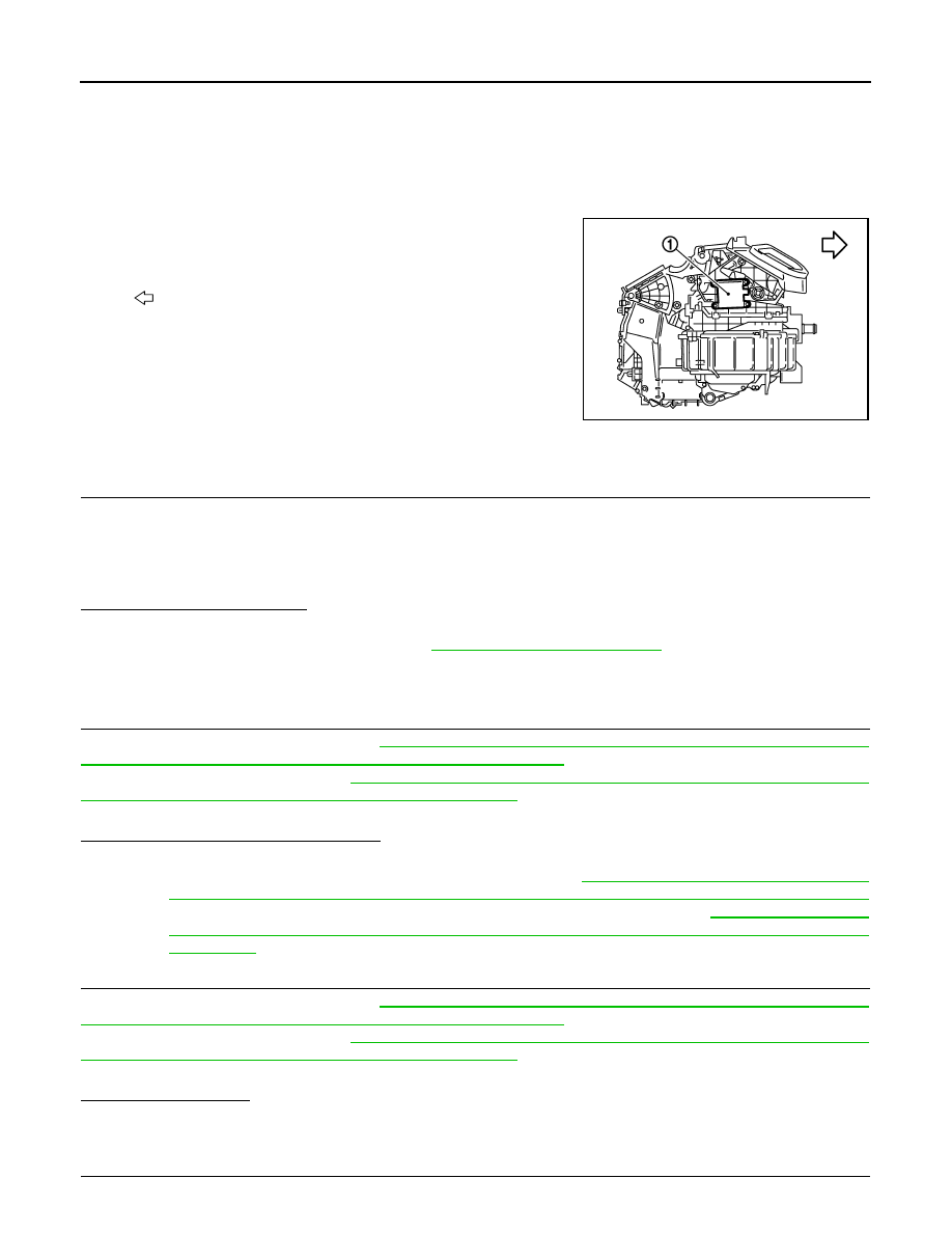
Intake Door Motor
The intake door motor (1) is attached to the blower unit. It rotates so
that air is drawn from inlets set by the unified meter and A/C amp.
Motor rotation is conveyed to a lever which activates the intake door.
Component Function Check
INFOID:0000000000959938
1.
CONFIRM SYMPTOM BY PERFORMING THE FOLLOWING OPERATIONAL CHECK
1.
Press intake switch.
2.
REC indicator should illuminate.
3.
Listen for intake door position change (Slight change of blower sound can be heard.).
4.
Press intake switch again.
5.
FRE indicator should illuminate.
Is the inspection result normal?
YES
>> END.
NO
>> Go to diagnosis procedure. Refer to
Diagnosis Procedure
INFOID:0000000000959939
1.
PERFORM SELF-DIAGNOSIS STEP-2
Perform self-diagnosis STEP-2. Refer to
HAC-44, "WITHOUT LEFT AND RIGHT VENTILATION TEMPERA-
TURE SEPARATELY CONTROL SYSTEM : Diagnosis Description"
(Without left and right ventilation tempera-
ture separately control system) or
HAC-50, "WITH LEFT AND RIGHT VENTILATION TEMPERATURE
SEPARATELY CONTROL SYSTEM : Diagnosis Description"
(With left and right ventilation temperature sepa-
rately control system), see No. 1 to 2.
Does code No. 20 appear on the display?
YES
>> GO TO 2.
NO
>> .Go to appropriate malfunctioning sensor circuit. Refer to
HAC-44, "WITHOUT LEFT AND RIGHT
VENTILATION TEMPERATURE SEPARATELY CONTROL SYSTEM : Diagnosis Description"
(Without left and right ventilation temperature separately control system) or
AND RIGHT VENTILATION TEMPERATURE SEPARATELY CONTROL SYSTEM : Diagnosis
Description"
(With left and right ventilation temperature separately control system), see No. 11.
2.
PERFORM SELF-DIAGNOSIS STEP-4
Perform self-diagnosis STEP-4. Refer to
HAC-44, "WITHOUT LEFT AND RIGHT VENTILATION TEMPERA-
TURE SEPARATELY CONTROL SYSTEM : Diagnosis Description"
(Without left and right ventilation tempera-
ture separately control system) or
HAC-50, "WITH LEFT AND RIGHT VENTILATION TEMPERATURE
SEPARATELY CONTROL SYSTEM : Diagnosis Description"
(With left and right ventilation temperature sepa-
rately control system), see No. 1 to 5.
Is it operated normally?
YES
>> END.
NO
>> GO TO 3.
3.
CHECK INTAKE DOOR CONTROL LINKAGE
:
Vehicle front
JSIIA0007GB