Infiniti G35 (V35) Sedan. Manual - part 756
HA-58
< ON-VEHICLE REPAIR >
EVAPORATOR
EVAPORATOR
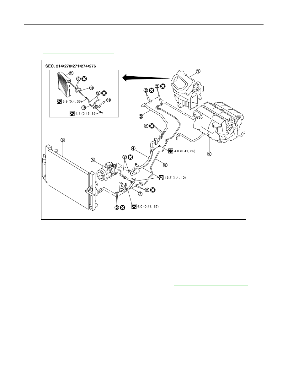
Exploded View
INFOID:0000000000959888
HA-17, "Refrigerant Connection"
.
Removal and Installation
INFOID:0000000000959889
REMOVAL
1.
Remove low-pressure pipe 1 and high-pressure pipe 2. Refer to
HA-51, "Removal and Installation"
CAUTION:
Cap or wrap the joint of expansion valve, low-pressure pipe 1 and high-pressure pipe 2 with suit-
able material such as vinyl tape to avoid the entry of air.
1.
Blower unit
2.
O-ring
3.
Low-pressure pipe 2
4.
Low-pressure flexible hose
5.
Compressor
6.
Radiator & condenser assembly
7.
High-pressure flexible hose
8.
High-pressure pipe 1
9.
Heater & cooling unit assembly
10. Expansion valve
11.
Evaporator
12. High-pressure pipe 2
13. Low-pressure pipe 1
JSIIA0109GB