Infiniti G35 (V35) Sedan. Manual - part 752


  Index      Infiniti     Infiniti G35 (V35) Sedan - service repair manual 2007 year


Search            


Content   ..  750  751  752  753   ..


Infiniti G35 (V35) Sedan. Manual - part 752


HA-42

< ON-VEHICLE REPAIR >

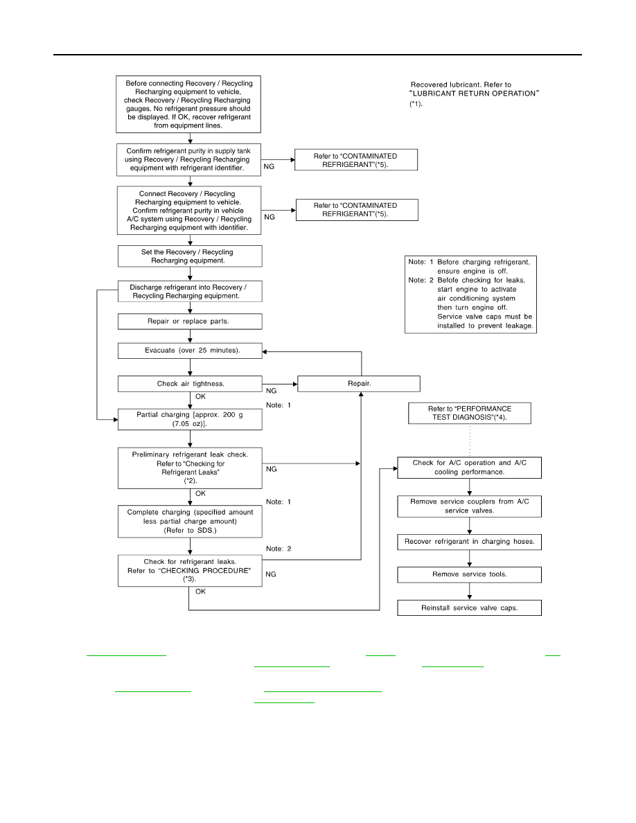
REFRIGERATION SYSTEM

*1

HA-30, "Adjustment"

*2

“REFRIGERANT LEAKS” in 

HA-34, 

"Refrigerant Leaks"

.

*3

“CHECKING PROCEDURE” in 

HA-

32, "Inspection"

.

*4

“PERFORMANCE TEST DIAGNO-
SIS” in 

HA-32, "Inspection"

.

*5

“CONTAMINATED REFRIGERANT” 
in 

HAC-129, "Working with HFC-

134a (R-134a)"

.

SJIA1275E

COMPRESSOR

HA-43

< ON-VEHICLE REPAIR >

C

D

E

F

G

H

J

K

L

M

A

B

HA

N

O

P

COMPRESSOR

Exploded View

INFOID:0000000000959869

Removal and Installation

INFOID:0000000000959870

REMOVAL

1.

Use a refrigerant collecting equipment (for HFC-134a) to discharge the refrigerant.

2.

Remove air cleaner case (LH) and air duct (LH). Refer to 

EM-25, "Removal and Installation"

.

3.

Remove engine undercover, using power tools.

4.

Drain engine coolant from radiator. Refer to 

CO-8, "Draining"

.

5.

Remove cooling fan assembly. Refer to 

CO-17, "Removal and Installation"

.

6.

Remove drive belt. Refer to 

EM-12, "Removal and Installation"

.

7.

Remove radiator hose (lower). Refer to 

CO-14, "Removal and Installation"

.

8.

Remove mounting nuts (A) from low-pressure flexible hose (1)
and high-pressure flexible hose (2).

CAUTION:

Cap or wrap the joint of compressor, low-pressure flexible
hose and high-pressure flexible hose with suitable material
such as vinyl tape to avoid the entry of air.

9.

Disconnect compressor (ECV) connector (A).

10. Disconnect compressor (magnet clutch) connector (B).

1.

Compressor

JSIIA0011GB

JSIIA0090ZZ

JSIIA0021ZZ

HA-44

< ON-VEHICLE REPAIR >

COMPRESSOR

11. Remove mounting bolts (A) from compressor (1), using power

tools.

12. Remove the compressor from top of the vehicle.

INSTALLATION

Installation is basically the reverse order of removal.

CAUTION:

• Replace O-rings of low-pressure flexible hose and high-pressure flexible hose with new ones, and

then apply compressor oil to it when installing it.

• When recharging refrigerant, check for leaks.

Inspection

INFOID:0000000000959871

CHECK DISC TO PULLEY CLEARANCE

Check the clearance (B) between pulley assembly (1) and clutch
disc (2) along the entire periphery with a feeler gauge (A).

If specified clearance is not obtained, replace compressor.

JSIIA0022ZZ

Standard

: Refer to 

HA-62, "Compressor"

JSIIA0087ZZ

LOW-PRESSURE FLEXIBLE HOSE AND PIPE 2

HA-45

< ON-VEHICLE REPAIR >

C

D

E

F

G

H

J

K

L

M

A

B

HA

N

O

P

LOW-PRESSURE FLEXIBLE HOSE AND PIPE 2

Exploded View

INFOID:0000000000959872

Refer to 

HA-17, "Refrigerant Connection"

.

Removal and Installation

INFOID:0000000000959873

REMOVAL

1.

Use a refrigerant collecting equipment (for HFC-134a) to discharge the refrigerant.

2.

Remove engine cover. Refer to 

EM-27, "Removal and Installation"

.

3.

Remove air cleaner case (LH) and air duct (LH). Refer to 

EM-25, "Removal and Installation"

.

4.

Remove cowl top cover. Refer to 

EXT-18, "Removal and Installation"

.

1.

Blower unit

2.

O-ring

3.

Low-pressure pipe 2

4.

Low-pressure flexible hose

5.

Compressor

6.

Radiator & condenser assembly

7.

High-pressure flexible hose

8.

High-pressure pipe 1

9.

Heater & cooling unit assembly

10. Expansion valve

11.

Evaporator

12. High-pressure pipe 2

13. Low-pressure pipe 1

JSIIA0109GB


Content   ..  750  751  752  753   ..