Infiniti G35 (V35) Sedan. Manual - part 716
SERVICE DATA AND SPECIFICATIONS (SDS)
FSU-21
< SERVICE DATA AND SPECIFICATIONS (SDS)
[2WD]
C
D
F
G
H
I
J
K
L
M
A
B
FSU
N
O
P
SERVICE DATA AND SPECIFICATIONS (SDS)
SERVICE DATA AND SPECIFICATIONS (SDS)
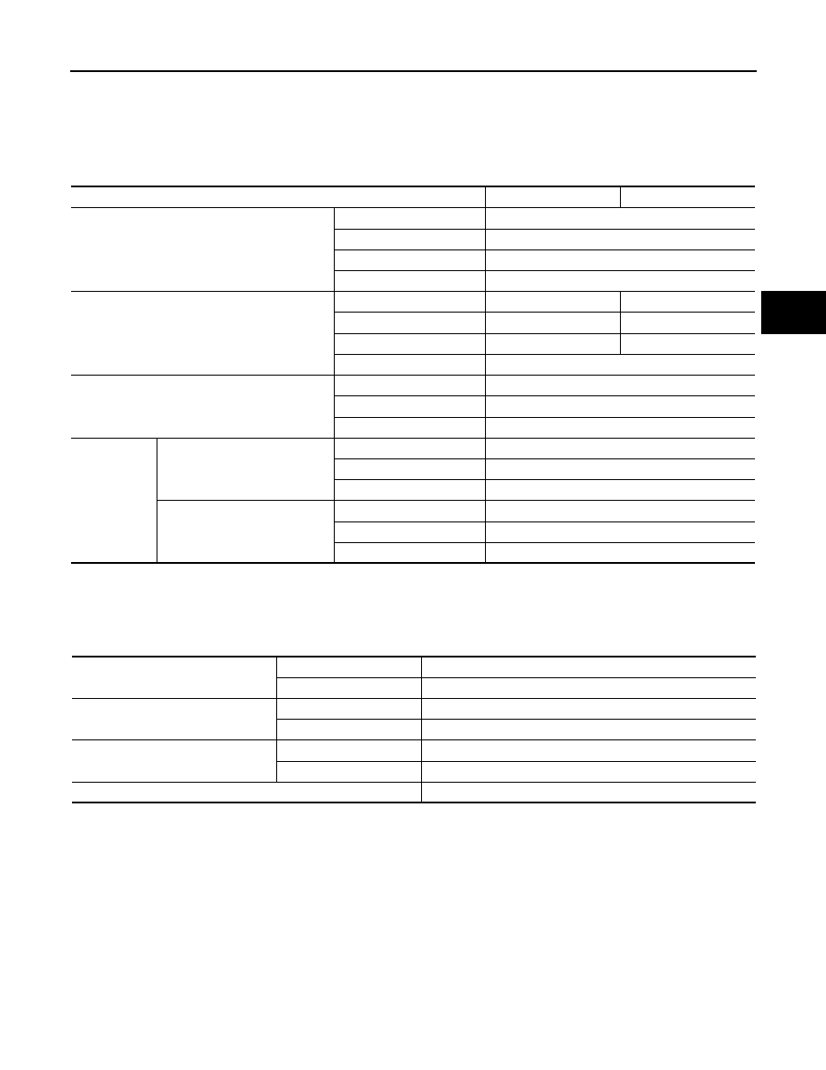
Wheel Alignment
INFOID:0000000000957786
Measure value under unladen* conditions.
*: Fuel, engine coolant and lubricant are full. Spare tire, jack, hand tools and mats are in designated positions.
Ball Joint
INFOID:0000000000957787
Wheel Height
INFOID:0000000000957788
Tire size
225/55R17
225/50R18
Camber
Degree minute (Decimal degree)
Minimum
–1
°
05
′
(–1.08
°
)
Nominal
–0
°
20
′
(–0.33
°
)
Maximum
0
°
25
′
(0.42
°
)
Left and right difference
0
°
33
′
(0.55
°
) or less
Caster
Degree minute (Decimal degree)
Minimum
3
°
50
′
(3.83
°
)
3
°
55
′
(3.92
°
)
Nominal
4
°
35
′
(4.58
°
)
4
°
40
′
(4.67
°
)
Maximum
5
°
20
′
(5.33
°
)
5
°
25
′
(5.42
°
)
Left and right difference
0
°
39
′
(0.65
°
) or less
Kingpin inclination
Degree minute (Decimal degree)
Minimum
6
°
35
′
(6.58
°
)
Nominal
7
°
20
′
(7.33
°
)
Maximum
8
°
05
′
(8.08
°
)
Total toe-in
Distance
Minimum
0 mm (0 in)
Nominal
1 mm (0.04 in)
Maximum
2 mm (0.08 in)
Angle (left wheel or right wheel)
Degree minute (Decimal Degree)
Minimum
0
°
00 (0.00
°
)
Nominal
0
°
02
′
30
″
(0.04
°
)
Maximum
0
°
05
′
(0.08
°
)
Swing torque
Transverse link
0.5 – 3.6 N·m (0.06 – 0.36 kg-m, 5 – 31 inlb)
Upper link
0 – 2.0 N·m (0 – 0.2 kg-m, 0 – 17 in-lb)
Measurement on spring balance
Transverse link
7.8 – 56.3 N (0.8 – 5.7 kg, 1.8 – 12.7 lb)
Upper link
0 – 61.5 N (0 – 6.3 kg, 0 – 13.8 lb)
Rotating torque
Transverse link
0.5 – 3.9 N·m (0.06 – 0.39 kg-m, 5 – 34 in-lb)
Upper link
0 – 2.0 N·m (0 – 0.2 kg-m, 0 – 17 in-lb)
Axial end play
0 mm (0 in)