Infiniti G35 (V35) Sedan. Manual - part 709


  Index      Infiniti     Infiniti G35 (V35) Sedan - service repair manual 2007 year


Search            


Content   ..  707  708  709  710   ..


Infiniti G35 (V35) Sedan. Manual - part 709


FL-8

< ON-VEHICLE REPAIR >

FUEL LEVEL SENSOR UNIT, FUEL FILTER AND FUEL PUMP ASSEMBLY

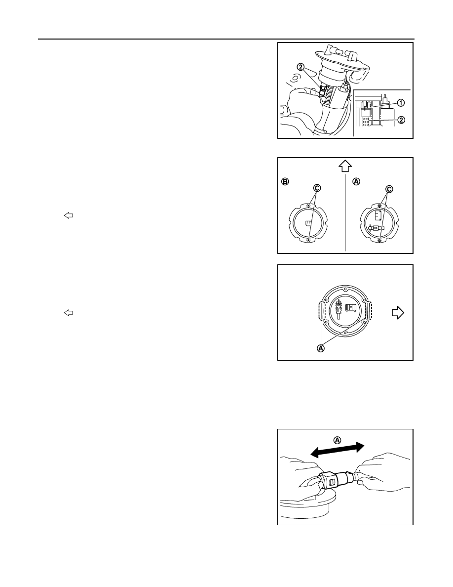
• When installing fuel hose connector (1) insert them fully until a

click sound of full stopper engagement is heard.

Main and Sub Fuel Level Sensor Unit

• Face main and sub fuel level sensor units as shown in the figure,

and install them with the knock pin (C) on back aligned with pin
hole on fuel tank.

• Install retainer so that its notch becomes parallel with the notch on

fuel tank.

• Tighten retainer mounting bolts evenly.

Quick Connector

• Connect quick connector as follows:
1.

Check the connection for damage or any foreign materials.

2.

Align the connector with the tube, then insert the connector straight into the tube until a click sound is
heard.

3.

After connecting, make sure that the connection is secure by following method.
• Pull the tube and the connector to make sure they are securely

connected.

• Visually confirm that the two retainer tabs are connected to the

connector.

Inspection

INFOID:0000000000956370

INSPECTION AFTER INSTALLATION

2

: Fuel hose

JPBIA0137ZZ

A

: Right side

B

: Left side

: Vehicle front

JPBIA0138ZZ

A

: Align notches

: Vehicle front

JPBIA0139ZZ

A

:  Pull

JPBIA0140ZZ

FUEL LEVEL SENSOR UNIT, FUEL FILTER AND FUEL PUMP ASSEMBLY

FL-9

< ON-VEHICLE REPAIR >

C

D

E

F

G

H

I

J

K

L

M

A

FL

N

P

O

Use the following procedure to check for fuel leaks.

1.

Turn ignition switch “ON” (with engine stopped), then check connections for leakage by applying fuel pres-
sure to fuel piping.

2.

Start engine and let it idle and make sure there are no fuel leaks at the fuel system connections.

FL-10

< ON-VEHICLE REPAIR >

FUEL TANK

FUEL TANK

Exploded View

INFOID:0000000000956371

Removal and Installation

INFOID:0000000000956372

WARNING:

Be sure to read “General Precautions” when working on the fuel system. Refer to 

GI-26, "General Pre-

cautions"

.

REMOVAL

• Drain fuel from fuel tank if necessary. Refer to 

FL-10, "Exploded View"

.

• Perform work on level place.
1.

Perform steps 2 to 7 of “REMOVAL” in “ FUEL LEVEL SENSOR UNIT, FUEL FILTER AND FUEL PUMP
ASSEMBLY” on main and sub fuel level sensor units. Refer to 

FL-5, "Exploded View"

.

2.

Remove exhaust front tube, center muffler and main muffler. Refer to 

EX-5, "Exploded View"

.

3.

Remove propeller shaft. Refer to 

DLN-86, "Exploded View"

 (M/T 2WD models) or 

DLN-93, "Exploded

View"

 (A/T 2WD models) or 

DLN-101, "Exploded View"

 (A/T AWD models).

4.

Remove parking rear brake cables. Refer to 

PB-9, "Exploded View"

.

5.

Remove rear suspension assembly. Refer to 

RSU-17, "Exploded View"

.

1.

Fuel filler cap

2.

Grommet

3.

Fuel filler tube

4.

Clamp

5.

Vent hose

6.

Vent tube

7.

Vent hose

8.

EVAP hose

9.

Clamp

10. Clamp

11.

Fuel filler hose

12. Fuel tank mounting band

13. Fuel tank protector

14.

Insulator

15. Fuel tank

Refer to 

GI-4, "Components"

 for to symbol marks in the figure.

JPBIA0155GB

FUEL TANK

FL-11

< ON-VEHICLE REPAIR >

C

D

E

F

G

H

I

J

K

L

M

A

FL

N

P

O

6.

Remove fuel tank protector.

7.

Disconnect fuel filler hose (1), vent hose (2) and EVAP hoses (3)
at fuel tank side.

8.

Support the lower part of fuel tank (1) with transmission jack (A).

CAUTION:

Support the position that fuel tank mounting bands do not
engage.

9.

Remove fuel tank mounting bands.

10. Supporting with hands, descend transmission jack carefully, and remove fuel tank.

CAUTION:

• Make sure that all connection points have been disconnected.
• Confirm there is no interference with vehicle.

11. Remove fuel filler tube, as necessary.

INSTALLATION

Note the following, and install in the reverse order of removal.
• Surely clamp fuel hoses and insert hose to the length below.

• Be sure hose clamp is not placed on swelled area of fuel tube.
• Tighten the clamp hand with the top mark until the mark is on the

bolt head flange “A”.

• To connect quick connector, refer to 

FL-4, "Quick Connector"

.

Inspection

INFOID:0000000000956373

INSPECTION AFTER INSTALLATION

Use the following procedure to check for fuel leaks.

4

: Fuel tank protector

: Vehicle front

JPBIA0144ZZ

JPBIA0145ZZ

Fuel filler hose 

: 35 mm (1.38 in)

The other hoses

: 25 mm (0.98 in)

JPBIA0146ZZ


Content   ..  707  708  709  710   ..