Infiniti G35 (V35) Sedan. Manual - part 624
REAR TIMING CHAIN CASE
EM-95
< DISASSEMBLY AND ASSEMBLY >
C
D
E
F
G
H
I
J
K
L
M
A
EM
N
P
O
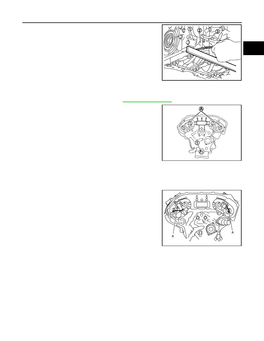
f.
After installing rear timing chain case, check the surface height
difference between the following parts on the oil pan (upper)
mounting surface.
• If not within the standard, repeat the installation procedure.
3.
Install water pump with new O-rings. Refer to
.
4.
Make sure that dowel pin (A) and crankshaft key (1) are located
as shown in the figure. (No. 1 cylinder at compression TDC)
NOTE:
Though camshaft does not stop at the position as shown in the
figure, for the placement of cam nose, it is generally accepted
camshaft is placed for the same direction of the figure.
5.
Install timing chains (secondary) and camshaft sprockets as follows:
CAUTION:
Mating marks between timing chain and sprockets slip easily. Confirm all mating mark positions
repeatedly during the installation process.
a.
Push plunger of timing chain tensioner (secondary) and keep it
pressed in with a stopper pin (A).
6.
For the following operations, perform steps in the reverse order of removal.
1
: Front timing chain case
2
: Rear timing chain case
3
: Lower cylinder block
Standard
Rear timing chain case to lower cylinder block:
–0.24 to 0.14 mm (–0.0094 to 0.0055 in)
JPBIA0093ZZ
Camshaft dowel pin
: At cylinder head upper face side in each bank.
Crankshaft key
: At cylinder head side of right bank.
JPBIA0094ZZ
JPBIA0095ZZ