Infiniti G35 (V35) Sedan. Manual - part 597
EC-534
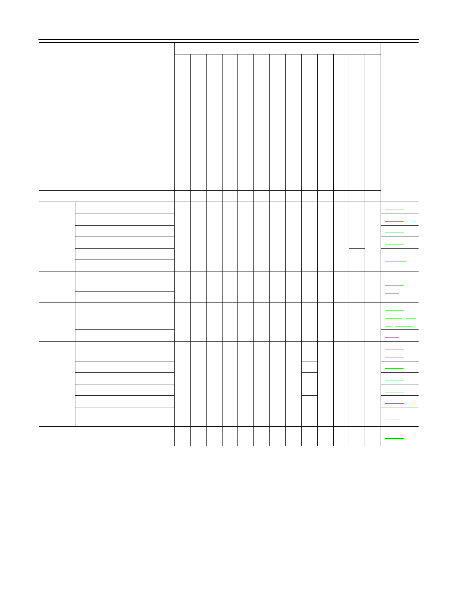
< SYMPTOM DIAGNOSIS >
[VQ35HR]
ENGINE CONTROL SYSTEM SYMPTOMS
1 - 6: The numbers refer to the order of inspection.
Valve
mecha-
nism
Timing chain
5
5
5
5
5
5
5
5
Camshaft
Intake valve timing control
Exhaust valve timing control
Intake valve
3
Exhaust valve
Exhaust
Exhaust manifold/Tube/Muffler/
Gasket
5
5
5
5
5
5
5
5
,
Three way catalyst
Lubrica-
tion
Oil pan/Oil strainer/Oil pump/Oil
filter/Oil gallery/Oil cooler
5
5
5
5
5
5
5
5
,
,
Oil level (Low)/Filthy oil
Cooling
Radiator/Hose/Radiator filler cap
5
5
5
5
5
5
5
4
5
,
Thermostat
5
Water pump
Water gallery
Cooling fan
5
Coolant level (Low)/Contaminat-
ed coolant
IVIS (INFINITI Vehicle Immobilizer System —
NATS)
1
1
SYMPTOM
Reference
page
HARD/NO S
T
A
R
T/RES
T
A
R
T (E
XCP
. HA)
E
N
GINE
ST
ALL
HES
IT
A
TION/SURGING/FLA
T
SPOT
S
P
ARK KNOC
K
/DET
O
NA
TI
ON
LACK OF
POWER/POOR ACCELERA
TION
HIG
H
IDL
E
/L
OW
ID
LE
ROUGH IDLE/HUNTING
ID
LING VI
BRA
T
ION
S
L
OW/NO RETU
RN
T
O
ID
LE
OVERHEA
T
S
/W
A
TER TEMPERA
T
URE HIG
H
E
X
CESSIVE
FUEL CON
S
UMP
T
ION
E
X
CESSIVE
OIL
C
O
NSUMP
T
ION
B
A
TTER
Y
DEAD (UNDER CHARGE)
Warranty symptom code
AA
AB
AC
AD
AE
AF
AG
AH
AJ
AK
AL
AM
HA