Infiniti G35 (V35) Sedan. Manual - part 575
EC-446
< COMPONENT DIAGNOSIS >
[VQ35HR]
ASCD BRAKE SWITCH
14.
CHECK ASCD CLUTCH SWITCH
EC-446, "Component Inspection (ASCD Clutch Switch)"
Is the inspection result normal?
YES
>> GO TO 15.
NO
>> Replace ASCD clutch switch.
15.
CHECK INTERMITTENT INCIDENT
GI-39, "Intermittent Incident"
>> INSPECTION END
Component Inspection (ASCD Brake Switch)
INFOID:0000000000956851
1.
CHECK ASCD BRAKE SWITCH-I
1.
Turn ignition switch OFF.
2.
Disconnect ASCD brake switch harness connector.
3.
Check the continuity between ASCD brake switch terminals under the following conditions.
Is the inspection result normal?
YES
>> INSPECTION END
NO
>> GO TO 2.
2.
CHECK ASCD BRAKE SWITCH-II
1.
Adjust ASCD brake switch installation. Refer to
BR-7, "Inspection and Adjustment"
.
2.
Check the continuity between ASCD brake switch terminals under the following conditions.
Is the inspection result normal?
YES
>> INSPECTION END
NO
>> Replace ASCD brake switch.
Component Inspection (ASCD Clutch Switch)
INFOID:0000000000956852
1.
CHECK ASCD CLUTCH SWITCH-I
1.
Turn ignition switch OFF.
2.
Disconnect ASCD clutch switch harness connector.
3.
Check the continuity between ASCD clutch switch terminals under the following conditions.
Is the inspection result normal?
YES
>> INSPECTION END
NO
>> GO TO 2.
2.
CHECK ASCD CLUTCH SWITCH-II
1.
Adjust ASCD clutch switch installation. Refer to
CL-5, "Inspection and Adjustment"
.
2.
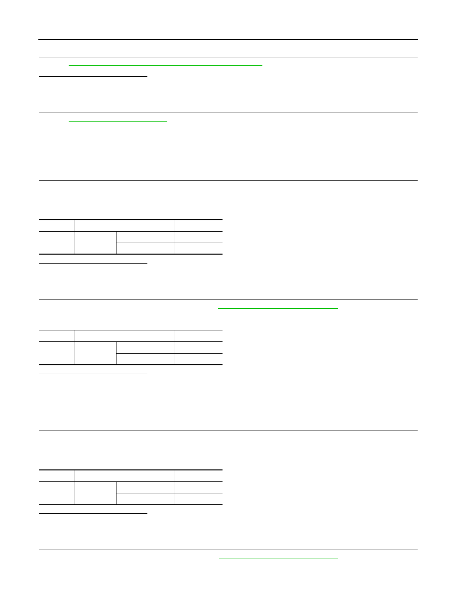
Check the continuity between ASCD clutch switch terminals under the following conditions.
Terminals
Condition
Continuity
1 and 2
Brake pedal
Fully released
Existed
Slightly depressed
Not existed
Terminals
Condition
Continuity
1 and 2
Brake pedal
Fully released
Existed
Slightly depressed
Not existed
Terminals
Condition
Continuity
1 and 2
Clutch pedal
Fully released
Existed
Slightly depressed
Not existed