Infiniti G35 (V35) Sedan. Manual - part 528


  Index      Infiniti     Infiniti G35 (V35) Sedan - service repair manual 2007 year


Search            


Content   ..  526  527  528  529   ..


Infiniti G35 (V35) Sedan. Manual - part 528


EC-258

< COMPONENT DIAGNOSIS >

[VQ35HR]

P0340, P0345 CMP SENSOR (PHASE)

P0340, P0345 CMP SENSOR (PHASE)

Description

INFOID:0000000000956646

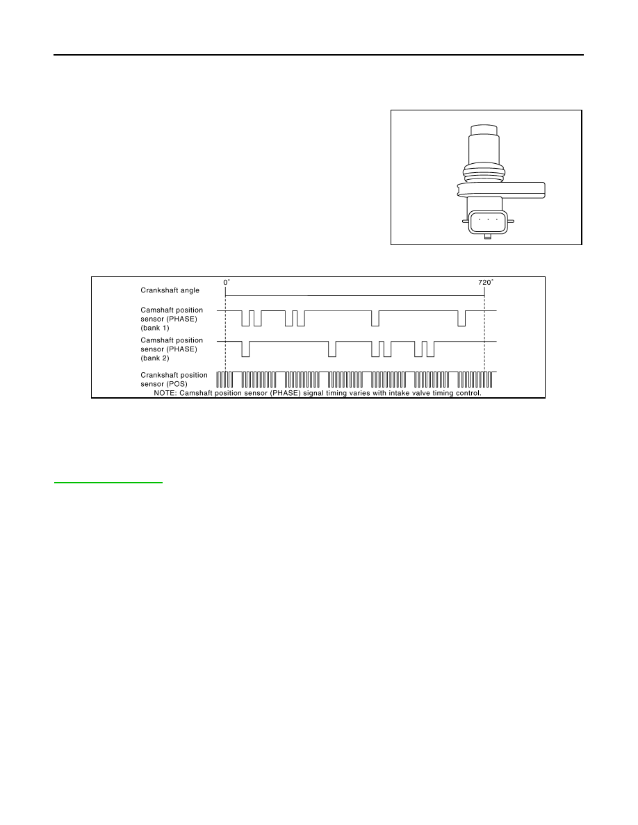
The camshaft position sensor (PHASE) senses the retraction of
camshaft (INT) to identify a particular cylinder. The camshaft position
sensor (PHASE) senses the piston position.
When the crankshaft position sensor (POS) system becomes inoper-
ative, the camshaft position sensor (PHASE) provides various con-
trols of engine parts instead, utilizing timing of cylinder identification
signals.
The sensor consists of a permanent magnet and Hall IC.
When engine is running, the high and low parts of the teeth cause
the gap with the sensor to change.
The changing gap causes the magnetic field near the sensor to
change.
Due to the changing magnetic field, the voltage from the sensor changes. 
ECM receives the signals as shown in the figure.

DTC Logic

INFOID:0000000000956647

DTC DETECTION LOGIC

NOTE:
If DTC P0340 is displayed with DTC P0643, first perform the trouble diagnosis for DTC P0643. Refer to

EC-340, "DTC Logic"

.

JMBIA0064ZZ

JMBIA0001GB

P0340, P0345 CMP SENSOR (PHASE)

EC-259

< COMPONENT DIAGNOSIS >

[VQ35HR]

C

D

E

F

G

H

I

J

K

L

M

A

EC

N

P

O

DTC CONFIRMATION PROCEDURE

1.

PRECONDITIONING

If DTC Confirmation Procedure has been previously conducted, always turn ignition switch OFF and wait at
least 10 seconds before conducting the next test.
TESTING CONDITION:
Before performing the following procedure, confirm that battery voltage is more than 10.5V with igni-
tion switch ON.

>> GO TO 2.

2.

PERFORM DTC CONFIRMATION PROCEDURE-I

1.

Start engine and let it idle for at least 5 seconds.
If engine does not start, crank engine for at least 2 seconds.

2.

Check 1st trip DTC.

Is 1st trip DTC detected?

YES

>> Go to 

EC-260, "Diagnosis Procedure"

.

NO

>> GO TO 3.

3.

PERFORM DTC CONFIRMATION PROCEDURE-I

1.

Maintaining engine speed at more than 800 rpm for at least 5 seconds.

2.

Check 1st trip DTC.

Is 1st trip DTC detected?

YES

>> Go to 

EC-260, "Diagnosis Procedure"

.

NO

>> INSPECTION END

DTC No.

Trouble diagnosis name

DTC detecting condition

Possible cause

P0340

Camshaft position sen-
sor (PHASE) (bank 1) 
circuit

• The cylinder No. signal is not sent to ECM for 

the first few seconds during engine cranking.

• The cylinder No. signal is not sent to ECM 

during engine running.

• The cylinder No. signal is not in the normal 

pattern during engine running.

• Harness or connectors

[CMP sensor (PHASE) (bank 1) circuit is 
open or shorted.]

• Camshaft position sensor (PHASE) 

(bank 1)

• Camshaft  (INT)
• Starter motor
• Starting system circuit
• Dead (Weak) battery

P0345

Camshaft position sen-
sor (PHASE) (bank 2) 
circuit

• Harness or connectors

[CMP sensor (PHASE) (bank 2) circuit is 
open or shorted.]
[CKP sensor (POS) circuit is shorted.]
[EVT control position sensor (bank 2) cir-
cuit is shorted.]
(Battery current sensor circuit is shorted.)
(APP sensor 2 circuit is shorted.)
(EVAP control system pressure sensor 
circuit is shorted.)
(Refrigerant pressure sensor circuit is 
shorted.)

• Camshaft position sensor (PHASE) 

(bank 2)

• Crankshaft position sensor (POS)
• Exhaust valve timing control position sen-

sor (bank 2)

• Battery current sensor
• Accelerator pedal position sensor
• EVAP control system pressure sensor
• Refrigerant pressure sensor
• Camshaft  (INT)
• Starter motor
• Starting system circuit
• Dead (Weak) battery

EC-260

< COMPONENT DIAGNOSIS >

[VQ35HR]

P0340, P0345 CMP SENSOR (PHASE)

Diagnosis Procedure

INFOID:0000000000956648

1.

CHECK STARTING SYSTEM

Turn ignition switch to START position.

Does the engine turn over? Does the starter motor operate?

YES

>> GO TO 2.

NO

>> Check starting system. (Refer to 

STR-2, "Work Flow"

.)

2.

CHECK GROUND CONNECTION

1.

Turn ignition switch OFF.

2.

Check ground connection M95. Refer to Ground Inspection in 

GI-42, "Circuit Inspection"

.

Is the inspection result normal?

YES

>> GO TO 3.

NO

>> Repair or replace ground connection.

3.

CHECK CAMSHAFT POSITION (CMP) SENSOR (PHASE) POWER SUPPLY CIRCUIT-I

1.

Disconnect camshaft position (CMP) sensor (PHASE) harness connector.

2.

Turn ignition switch ON.

3.

Check the voltage between CMP sensor (PHASE) harness connector and ground.

Is the inspection result normal?

YES

>> GO TO 9.

NO-1

>> P0340: Repair open circuit or short to ground or short to power in harness or connectors.

NO-2

>> P0345: GO TO 4.

4.

CHECK CAMSHAFT POSITION (CMP) SENSOR (PHASE) POWER SUPPLY CIRCUIT-II

1.

Turn ignition switch OFF.

2.

Disconnect ECM harness connector.

3.

Check the continuity between CMP sensor (PHASE) harness connector and ECM harness connector.

Is the inspection result normal?

YES

>> GO TO 5.

NO

>> Repair open circuit.

5.

CHECK CAMSHAFT POSITION (CMP) SENSOR (PHASE) POWER SUPPLY CIRCUIT-III

Check harness for short to power and short to ground, between the following terminals.

DTC

CMP sensor (PHASE)

Ground

Voltage

Bank

Connector

Terminal

P0340

1

F5

1

Ground

Approx. 5V

P0345

2

F18

1

CMP sensor (PHASE)

ECM

Continuity

Bank

Connector

Terminal

Connector

Terminal

2

F18

1

F102

64

Existed

ECM

Sensor

Connector

Terminal

Name

Connector

Terminal

F101

46

CKP sensor (POS)

F2

1

F102

64

CMP sensor (PHASE) (bank 2)

F18

1

EVT control position sensor (bank 2)

F19

1

Battery current sensor

E21

1

P0340, P0345 CMP SENSOR (PHASE)

EC-261

< COMPONENT DIAGNOSIS >

[VQ35HR]

C

D

E

F

G

H

I

J

K

L

M

A

EC

N

P

O

Is the inspection result normal?

YES

>> GO TO 6.

NO

>> Repair short to ground or short to power in harness or connectors.

6.

CHECK COMPONENTS

Check the following.
• Crankshaft position sensor (POS) (Refer to 

EC-257, "Component Inspection"

.)

• Exhaust valve timing control position sensor (bank 2) (Refer to 

EC-350, "Component Inspection"

.)

• Battery current sensor (Refer to 

EC-381, "Component Inspection"

.)

• EVAP control system pressure sensor (Refer to 

EC-298, "Component Inspection"

.)

• Refrigerant pressure sensor (Refer to 

HAC-92, "Component Inspection"

.)

Is the inspection result normal?

YES

>> GO TO 7.

NO

>> Replace malfunctioning component.

7.

CHECK APP SENSOR

Refer to 

EC-427, "Component Inspection"

.

Is the inspection result normal?

YES

>> GO TO 15.

NO

>> GO TO 8.

8.

REPLACE ACCELERATOR PEDAL ASSEMBLY

1.

Replace accelerator pedal assembly.

2.

Go to 

EC-427, "Special Repair Requirement"

.

>> INSPECTION END

9.

CHECK CMP SENSOR (PHASE) GROUND CIRCUIT FOR OPEN AND SHORT

1.

Turn ignition switch OFF.

2.

Disconnect ECM harness connector.

3.

Check the continuity between CMP sensor (PHASE) harness connector and ECM harness connector.

4.

Also check harness for short to ground and short to power.

Is the inspection result normal?

YES

>> GO TO 11.

NO

>> GO TO 10.

10.

DETECT MALFUNCTIONING PART

Check the following.
• Harness connectors F107, F106
• Harness for open or short between CMP sensor (PHASE) and ECM

>> Repair open circuit or short to ground or short to power in harness or connectors.

11.

CHECK CMP SENSOR (PHASE) INPUT SIGNAL CIRCUIT FOR OPEN AND SHORT

M107

103

APP sensor

E112

6

107

EVAP control system pressure sensor

B252

3

111

Refrigerant pressure sensor

E77

3

ECM

Sensor

Connector

Terminal

Name

Connector

Terminal

DTC

CMP sensor (PHASE)

ECM

Continuity

Bank

Connector

Terminal

Connector

Terminal

P0340

1

F5

2

F102

92

Existed

P0345

2

F18

2

96


Content   ..  526  527  528  529   ..