Infiniti G35 (V35) Sedan. Manual - part 482


  Index      Infiniti     Infiniti G35 (V35) Sedan - service repair manual 2007 year


Search            


Content   ..  480  481  482  483   ..


Infiniti G35 (V35) Sedan. Manual - part 482


EC-74

< FUNCTION DIAGNOSIS >

[VQ35HR]

COOLING FAN CONTROL

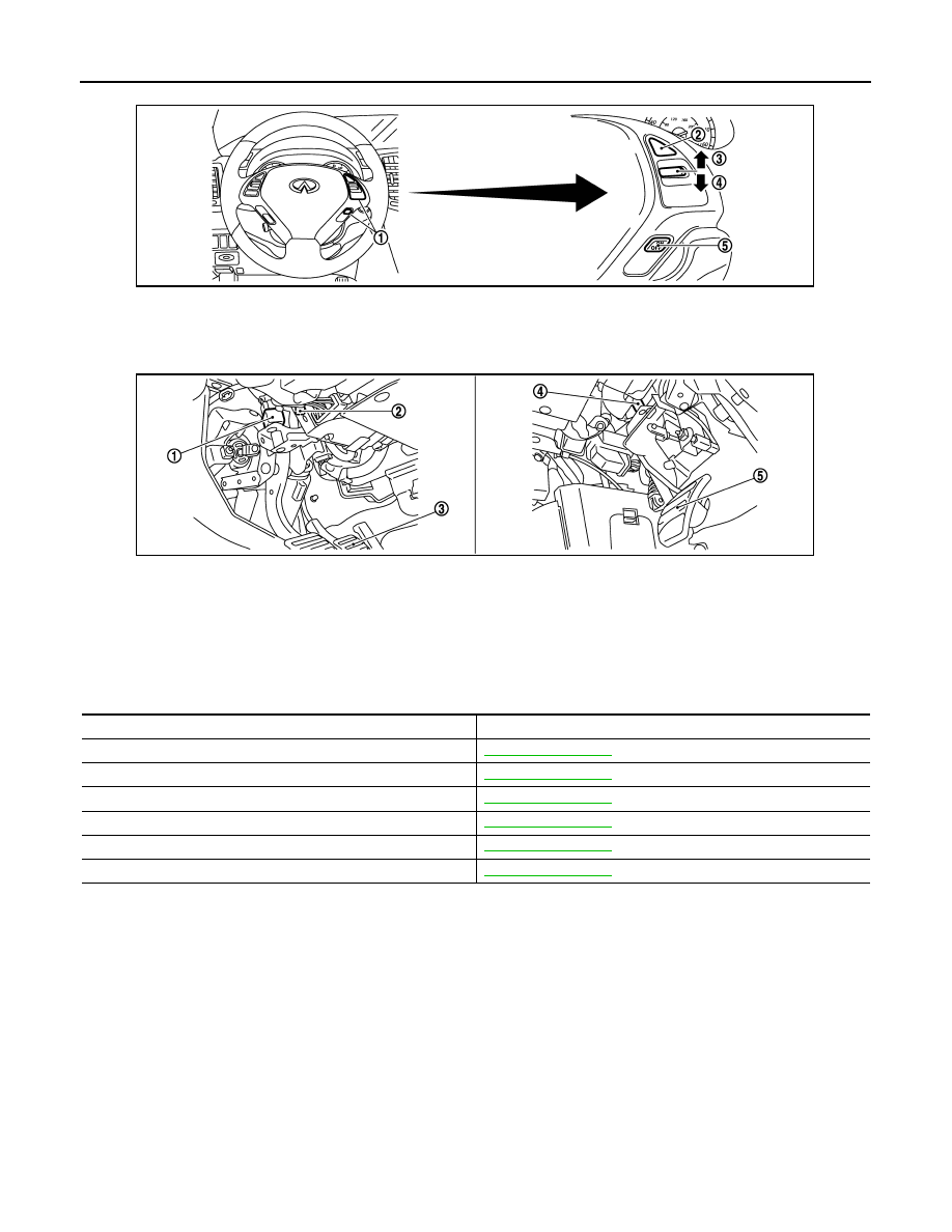
Component Description

INFOID:0000000000956502

1.

ASCD steering switch

2.

CANCEL switch

3.

RESUME/ACCELERATE switch

4.

SET/COAST switch

5.

MAIN switch

1.

Stop lamp switch

2.

ASCD brake switch (ASCD models)
ICC brake switch (ICC models)

3.

Brake pedal

4.

ASCD clutch switch (ASCD models)
ICC clutch switch (ICC models)

5.

Clutch pedal

JMBIA0017ZZ

JMBIA0051ZZ

Component

Reference

Camshaft position sensor (PHASE)

EC-258, "Description"

Crankshaft position sensor (POS)

EC-254, "Description"

Cooling fan control module

EC-449, "Description"

Cooling fan motor

EC-449, "Description"

Engine coolant temperature sensor

EC-174, "Description"

Refrigerant pressure sensor

EC-479, "Description"

EVAPORATIVE EMISSION SYSTEM

EC-75

< FUNCTION DIAGNOSIS >

[VQ35HR]

C

D

E

F

G

H

I

J

K

L

M

A

EC

N

P

O

EVAPORATIVE EMISSION SYSTEM

System Diagram

INFOID:0000000000956503

EVAPORATIVE EMISSION LINE DRAWING

PBIB1631E

1.

Intake manifold collector

2.

EVAP canister purge volume control 
solenoid valve

3.

EVAP service port

 : From next figure

JMBIA0052ZZ

EC-76

< FUNCTION DIAGNOSIS >

[VQ35HR]

EVAPORATIVE EMISSION SYSTEM

NOTE:
Do not use soapy water or any type of solvent while installing vacuum hose or purge hoses.

System Description

INFOID:0000000000956504

INPUT/OUTPUT SIGNAL CHART

 : Vehicle front

1.

EVAP canister

2.

EVAP canister vent control valve

3.

EVAP control system pressure sen-
sor

 : To previous figure

JMBIA0053ZZ

EVAPORATIVE EMISSION SYSTEM

EC-77

< FUNCTION DIAGNOSIS >

[VQ35HR]

C

D

E

F

G

H

I

J

K

L

M

A

EC

N

P

O

*1: ECM determines the start signal status by the signals of engine speed and battery voltage.

*2: This signal is sent to the ECM through CAN communication line.

SYSTEM DESCRIPTION

The evaporative emission system is used to reduce hydrocarbons emitted into the atmosphere from the fuel
system. This reduction of hydrocarbons is accomplished by activated charcoals in the EVAP canister.
The fuel vapor in the sealed fuel tank is led into the EVAP canister which contains activated carbon and the
vapor is stored there when the engine is not operating or when refueling to the fuel tank.
The vapor in the EVAP canister is purged by the air through the purge line to the intake manifold when the
engine is operating. EVAP canister purge volume control solenoid valve is controlled by ECM. When the
engine operates, the flow rate of vapor controlled by EVAP canister purge volume control solenoid valve is
proportionally regulated as the air flow increases.
EVAP canister purge volume control solenoid valve also shuts off the vapor purge line during decelerating and
idling.

Component Parts Location

INFOID:0000000000956505

Sensor

Input signal to ECM

ECM function

Actuator

Crankshaft position sensor (POS)
Camshaft position sensor (PHASE)

Engine speed*

1

EVAP canister 
purge flow control

EVAP canister purge vol-
ume control solenoid valve

Mass air flow sensor

Amount of intake air

Engine coolant temperature sensor

Engine coolant temperature

Battery

Battery voltage*

1

Throttle position sensor

Throttle position

Accelerator pedal position sensor

Accelerator pedal position

Air fuel ratio (A/F) sensor 1

Density of oxygen in exhaust gas
(Mixture ratio feedback signal)

Fuel tank temperature sensor

Fuel temperature in fuel tank

EVAP control system pressure sensor

Pressure in purge line

Unified meter and A/C amp.

Vehicle speed*

2


Content   ..  480  481  482  483   ..