Infiniti G35 (V35) Sedan. Manual - part 460


  Index      Infiniti     Infiniti G35 (V35) Sedan - service repair manual 2007 year


Search            


Content   ..  458  459  460  461   ..


Infiniti G35 (V35) Sedan. Manual - part 460


DLN-274

< DISASSEMBLY AND ASSEMBLY >

[REAR FINAL DRIVE: R200V]

DRIVE PINION

10. Apply anti-corrosion oil to the thread and seat of drive pinion

lock nut, and temporarily tighten drive pinion lock nut to drive
pinion.

CAUTION:

Never reuse drive pinion lock nut.

11. Adjust to the drive pinion lock nut tightening torque and pinion

bearing preload torque.

CAUTION:

• Adjust to the lower limit of the drive pinion lock nut tight-

ening torque first.

• If the preload torque exceeds the specified value, replace

collapsible spacer and tighten it again to adjust. Never
loosen drive pinion lock nut to adjust the preload torque.

• After adjustment, rotate drive pinion back and forth 2 to 3

times to check for unusual noise, rotation malfunction,
and other malfunctions.

12. Install differential case assembly. Refer to 

DLN-272, "M/T :

Assembly"

.

CAUTION:

Never install rear cover yet.

13. Check and adjust drive gear runout, tooth contact, drive gear to drive pinion backlash, and companion

flange runout. Refer to 

DLN-274, "M/T : Adjustment"

.

Recheck above items. Readjust the above description, if necessary.

14. Check total preload torque. Refer to 

DLN-274, "M/T : Adjustment"

.

15. Install rear cover. Refer to 

DLN-272, "M/T : Assembly"

.

M/T : Adjustment

INFOID:0000000000957455

PINION GEAR HEIGHT

1.

Make sure all parts are clean and that the bearings are well
lubricated.

2.

Assemble the pinion gear bearings into the differential shim
selector tool [SST: 

 (J-34309)].

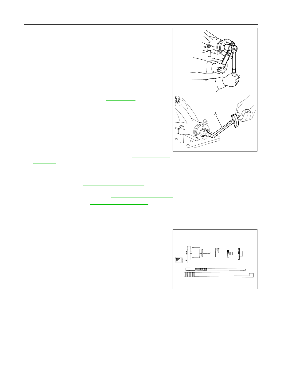
A: Preload gauge [SST: ST3127S000 (J-25765-A)]

Standard

Pinion bearing preload

: Refer to 

DLN-287, "Pre-

load Torque"

.

JSDIA0047ZZ

SPD769

DRIVE PINION

DLN-275

< DISASSEMBLY AND ASSEMBLY >

[REAR FINAL DRIVE: R200V]

C

E

F

G

H

I

J

K

L

M

A

B

DLN

N

O

P

• Pinion front bearing; make sure the J-34309-3 pinion front

bearing seat is secured tightly against the J-34309-2 gauge
anvil. Then turn the pinion front bearing pilot, J-34309-5, to
secure the bearing in its proper position.

• Pinion rear bearing; the pinion rear bearing pilot, J-34309-8,

is used to center the pinion rear bearing only. The pinion rear
bearing locking seat, J-34309-4, is used to lock the bearing to
the assembly.

• Installation of J-34309-9 and J-34309-16; place a suitable

2.5 mm (0.098 in) thick plain washer between J-34309-9 and
J-34309-16. Both surfaces of J-34309-9 and J-34309-16 must
be parallel with a clearance of 2.5 mm (0.098 in).

3.

Install the pinion rear bearing inner race into gear carrier. Then
place the pinion preload shim selector tool, J-34309-1, gauge
screw assembly.

4.

Assemble the pinion front bearing inner race and the J-34309-2
gauge anvil. Assemble them together with the J-34309-1 gauge
screw in gear carrier. Make sure that the pinion height gauge
plate, J-34309-16, will turn a full 360 degrees. Tighten the two
sections together by hand.

5.

Turn the assembly several times to seat the bearings.

6.

Measure the turning torque at the end of the J-34309-2 gauge
anvil using preload gauge [SST: ST3127S000 (J-25765-A)].

SPD197A

SPD893

SPD199A

SPD770

Turning torque specifica-
tion

: 1.0 – 1.3 N·m (0.11 – 0.13 
kg-m, 9 – 11 in-lb)

PDIA0566E

DLN-276

< DISASSEMBLY AND ASSEMBLY >

[REAR FINAL DRIVE: R200V]

DRIVE PINION

7.

Place the J-34309-11 “R200A” pinion height adapter onto the
gauge plate and tighten it by hand.

CAUTION:

Make sure all machined surfaces are clean.

8.

Position the side bearing discs, J-25269-4, and arbor firmly into
the side bearing bores. Install the bearing caps and tighten bear-
ing cap mounting bolts to the specified torque.

9.

Select the correct standard pinion height adjusting washer thick-
ness. Select by using a standard gauge of 3 mm (0.12 in) and
your J-34309-101 feeler gauge. Measure the distance between
the J-34309-11 pinion height adapter including the standard
gauge and the arbor.

10. Write down exact measurement (the value of feeler gauge).

11. Correct the pinion height washer size by referring to the “pinion

head number”.
There are two numbers painted on the drive pinion. The first
one refers to the drive pinion and drive gear as a matched
set. This number should be the same as the number on the
drive gear. The second number is the “pinion head height
number”. It refers to the ideal pinion height from standard
for quietest operation. Use the following chart to determine
the correct pinion height washer.

SPD208A

SPD211A

SPD204A

SPD775

SPD542

DRIVE PINION

DLN-277

< DISASSEMBLY AND ASSEMBLY >

[REAR FINAL DRIVE: R200V]

C

E

F

G

H

I

J

K

L

M

A

B

DLN

N

O

P

12. Select the correct pinion height adjusting washer.
13. Remove the J-34309 differential shim selector tool from the final

drive housing. Then disassemble to retrieve the pinion bearings.

COMPANION FLANGE RUNOUT

1.

Fit a dial indicator onto the companion flange face (inner side of
the propeller shaft mounting bolt holes).

2.

Rotate the companion flange to check for runout.

3.

Fit a test indicator to the inner side of the companion flange
(socket diameter).

4.

Rotate the companion flange to check for runout.

5.

If the runout value is outside the repair limit, follow the procedure below to adjust.

a.

Check for runout while changing the phase between companion flange and drive pinion gear by 90

°

 step,

and search for the position where the runout is the minimum.

b.

If the runout value is still outside of the limit after the phase has been changed, possible cause will be an
assembly malfunction of drive pinion and pinion bearing and malfunction of pinion bearing. Check for
these items and repair if necessary.

c.

If the runout value is still outside of the limit after the check and repair, replace companion flange.

M/T : Inspection After Disassembly

INFOID:0000000000957456

Pinion head height number

Add or remove from the standard pinion height ad-

justing washer thickness measurement

 6

 5

 4

 3

 2

 1

0

+1
+2
+3
+4
+5 
+6

Add 0.06 mm (0.0024 in)
Add 0.05 mm (0.0020 in)
Add 0.04 mm (0.0016 in)
Add 0.03 mm (0.0012 in)
Add 0.02 mm (0.0008 in)
Add 0.01 mm (0.0004 in)

Use the selected washer thickness

Subtract 0.01 mm (0.0004 in)
Subtract 0.02 mm (0.0008 in)
Subtract 0.03 mm (0.0012 in)
Subtract 0.04 mm (0.0016 in)
Subtract 0.05 mm (0.0020 in)
Subtract 0.06 mm (0.0024 in)

SPD205A

Limit

Companion flange runout

: Refer to 

DLN-287, "Com-

panion flange Runout (M/T 
Models)"

.

Limit

Companion flange runout

: Refer to 

DLN-287, "Com-

panion flange Runout (M/T 
Models)"

.

JSDIA0116ZZ


Content   ..  458  459  460  461   ..