Infiniti G35 (V35) Sedan. Manual - part 452
DLN-242
< ON-VEHICLE REPAIR >
[REAR FINAL DRIVE: R200V]
SIDE OIL SEAL
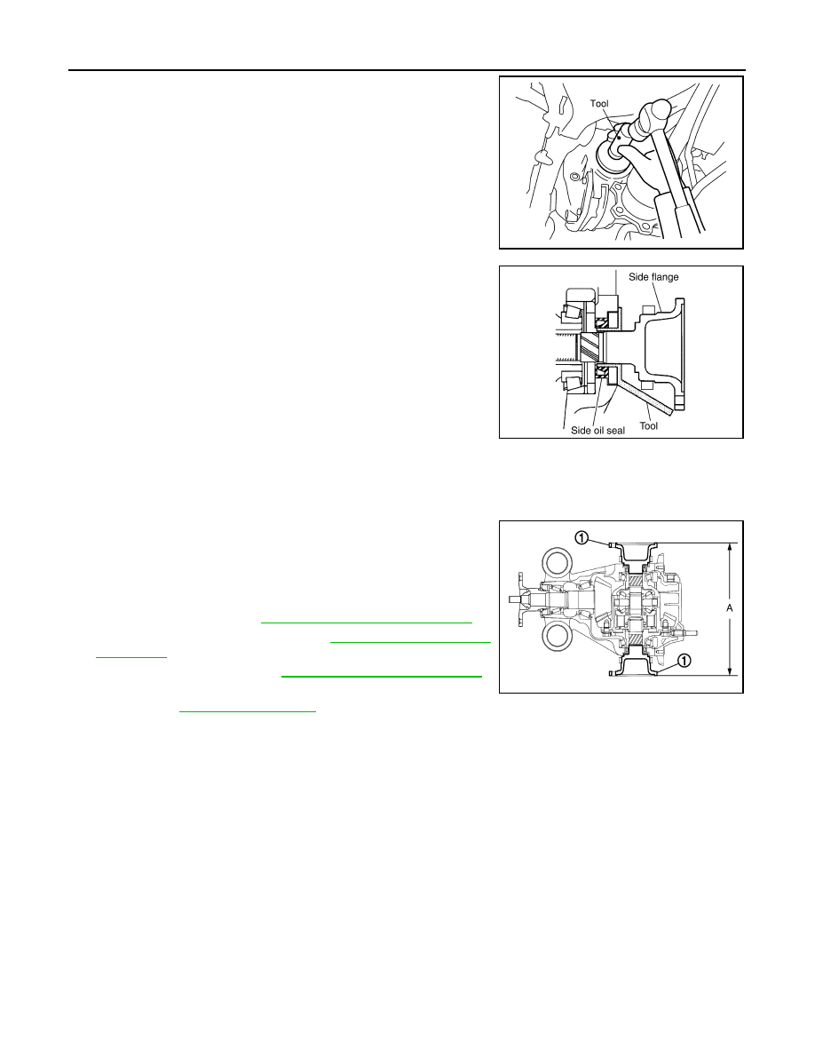
2.
Install side oil seal until it becomes flush with the case end,
using the drift [SST: KV38100200 (J-26233)].
CAUTION:
• Never reuse oil seal.
• When installing, never incline oil seal.
3.
Install side flange with the following procedure.
a.
Attach the protector [SST: KV38107900 (J-39352)] to side oil
seal.
b.
After the side flange is inserted and the serrated part of side
gear has engaged the serrated part of flange, remove the pro-
tector.
c.
Put a suitable drift on the center of side flange, then drive it until sound changes.
NOTE:
When installation is completed, driving sound of the side flange turns into a sound which seems to affect
the whole final drive.
d.
Confirm that the dimension of the side flange (1) installation
(Measurement A) in the figure comes into the following.
4.
Install drive shaft. Refer to
RAX-9, "Removal and Installation"
.
5.
Install rear wheel sensor. Refer to
.
6.
Install center muffler. Refer to
EX-5, "Removal and Installation"
.
7.
When oil leaks while removing, check oil level after the installa-
tion. Refer to
.
SDIA1585E
SDIA0822E
Measurement “A”
: 326 – 328 mm (12.83 –
12.91 in)
JSDIA0110ZZ