Infiniti G35 (V35) Sedan. Manual - part 434


  Index      Infiniti     Infiniti G35 (V35) Sedan - service repair manual 2007 year


Search            


Content   ..  432  433  434  435   ..


Infiniti G35 (V35) Sedan. Manual - part 434


DLN-170

< ON-VEHICLE REPAIR >

[REAR FINAL DRIVE: R200]

SIDE OIL SEAL

3.

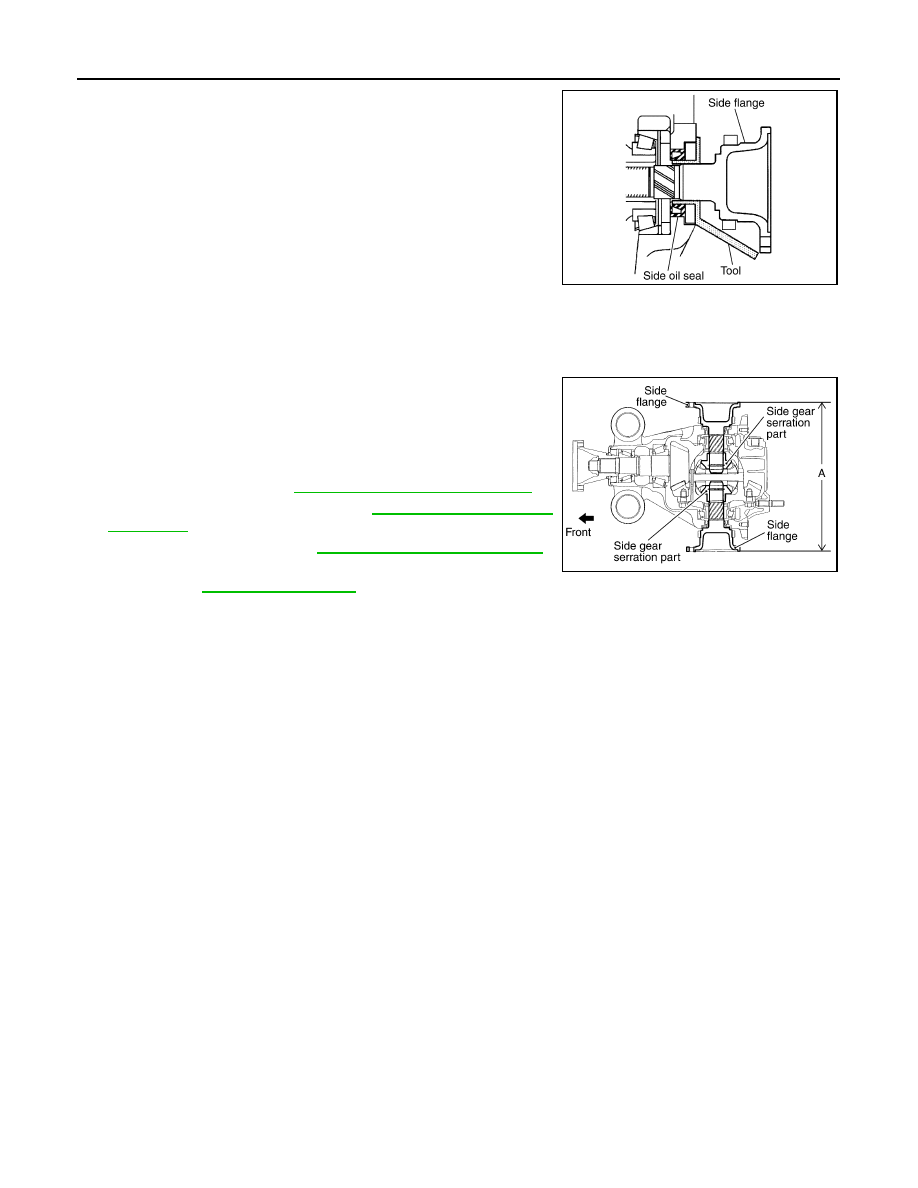
Install side flange with the following procedure.

a.

Attach the protector [SST: KV38107900 (J-39352)] to side oil
seal.

b.

After the side flange is inserted and the serrated part of side
gear has engaged the serrated part of flange, remove the pro-
tector.

c.

Put a suitable drift on the center of side flange, then drive it until sound changes.
NOTE:
When installation is completed, driving sound of the side flange turns into a sound which seems to affect
the whole final drive.

d.

Confirm that the dimension of the side flange installation (Mea-
surement A) in the figure comes into the following.

4.

Install drive shaft. Refer to 

RAX-9, "Removal and Installation"

.

5.

Install rear wheel sensor. Refer to 

BRC-100, "Removal and

Installation"

.

6.

Install center muffler. Refer to 

EX-5, "Removal and Installation"

.

7.

When oil leaks while removing, check oil level after the installa-
tion. Refer to 

DLN-154, "Inspection"

.

SDIA0822E

Measurement “A”

: 326 – 328 mm (12.83 – 
12.91 in)

SDIA1039E

REAR FINAL DRIVE ASSEMBLY

DLN-171

< REMOVAL AND INSTALLATION >

[REAR FINAL DRIVE: R200]

C

E

F

G

H

I

J

K

L

M

A

B

DLN

N

O

P

REMOVAL AND INSTALLATION

REAR FINAL DRIVE ASSEMBLY

2WD

2WD : Exploded View

INFOID:0000000000957391

2WD : Removal and Installation

INFOID:0000000000957392

REMOVAL

1.

Remove center muffler with a power tool. Refer to 

EX-5, "Removal and Installation"

.

2.

Remove rear stabilizer bar with a power tool. Refer to 

RSU-15, "Removal and Installation"

.

3.

Remove propeller shaft from the final drive. Refer to 

DLN-93, "Removal and Installation"

.

4.

Remove drive shaft from final drive with a power tool. Then sus-
pend it by wire etc. Refer to 

RAX-9, "Removal and Installation"

.

5.

Remove breather hose from the final drive.

6.

Remove rear wheel sensor. Refer to 

BRC-100, "Removal and

Installation"

.

1.

Rear final drive assembly

2.

Upper stopper

3.

Lower stopper

4.

Washer

: Vehicle front

Refer to 

GI-4, "Components"

 for symbols in the figure.

JSDIA0025GB

SDIA1094E

DLN-172

< REMOVAL AND INSTALLATION >

[REAR FINAL DRIVE: R200]

REAR FINAL DRIVE ASSEMBLY

7.

Set a suitable jack to rear final drive assembly.

CAUTION:

Never place a suitable jack on the rear cover (aluminum
case).

8.

Remove the mounting bolts and nuts connecting to the suspen-
sion member, and remove rear final drive assembly with a power
tool.

CAUTION:

Secure rear final drive assembly to a suitable jack while
removing it.

INSTALLATION

Note the following, and installation is in the reverse order of removal.
• When installing breather hoses (1), refer to the figure.

CAUTION:

Make sure there are no pinched or restricted areas on the
breather hose caused by bending or winding when installing
it.

- For installation, the vehicle side end shall be inserted to suspen-

sion member (2). Install metal connector (3) side of this hose to
rear cover by inserting it with aiming painted marking to the front of
vehicle.

• When oil leaks while removing final drive assembly, check oil level

after the installation. Refer to 

DLN-154, "Inspection"

.

AWD

AWD : Exploded View

INFOID:0000000000957393

AWD : Removal and Installation

INFOID:0000000000957394

JSDIA0026ZZ

: Vehicle front

PDIA0754E

1.

Rear final drive assembly

2.

Upper stopper

3.

Lower stopper

4.

Washer

: Vehicle front

Refer to 

GI-4, "Components"

 for symbols in the figure.

JSDIA0024GB

REAR FINAL DRIVE ASSEMBLY

DLN-173

< REMOVAL AND INSTALLATION >

[REAR FINAL DRIVE: R200]

C

E

F

G

H

I

J

K

L

M

A

B

DLN

N

O

P

REMOVAL

1.

Remove center muffler with a power tool. Refer to 

EX-5, "Removal and Installation"

.

2.

Remove rear stabilizer bar with a power tool. Refer to 

RSU-15, "Removal and Installation"

.

3.

Remove propeller shaft from the final drive. Refer to 

DLN-93, "Removal and Installation"

.

4.

Remove drive shaft from final drive with a power tool. Then sus-
pend it by wire etc. Refer to 

RAX-9, "Removal and Installation"

.

5.

Remove breather hose from the final drive.

6.

Remove rear wheel sensor. Refer to 

BRC-100, "Removal and

Installation"

.

7.

Set a suitable jack to rear final drive assembly.

CAUTION:

Never place a suitable jack on the rear cover (aluminum
case).

8.

Remove the mounting bolts and nuts connecting to the suspen-
sion member, and remove rear final drive assembly with a power
tool.

CAUTION:

Secure rear final drive assembly to a suitable jack while
removing it.

INSTALLATION

Note the following, and installation is in the reverse order of removal.
• When installing breather hoses (1), refer to the figure.

CAUTION:

Make sure there are no pinched or restricted areas on the
breather hose caused by bending or winding when installing
it.

- For installation, the vehicle side end shall be inserted to suspen-

sion member (2). Install metal connector (3) side of this hose to
rear cover by inserting it with aiming painted marking to the front of
vehicle.

• When oil leaks while removing final drive assembly, check oil level

after the installation. Refer to 

DLN-154, "Inspection"

.

SDIA1094E

JSDIA0131ZZ

: Vehicle front

PDIA0754E


Content   ..  432  433  434  435   ..