Infiniti G35 (V35) Sedan. Manual - part 240


  Index      Infiniti     Infiniti G35 (V35) Sedan - service repair manual 2007 year


Search            


Content   ..  238  239  240  241   ..


Infiniti G35 (V35) Sedan. Manual - part 240


BRC-34

< COMPONENT DIAGNOSIS >

[VDC/TCS/ABS]

C1105, C1106, C1107, C1108 WHEEL SENSOR-2

• Check wheel sensor for damage, disconnection or looseness.

Are the sensor and sensor rotor normal?

YES

>> GO TO 3.

NO

>> Repair wheel sensor mount or replace sensor rotor. Then perform the self-diagnosis.

3.

CHECK CONNECTOR

1.

Turn ignition switch OFF.

2.

Disconnect ABS actuator and electric unit (control unit) connector.

3.

Disconnect malfunctioning wheel sensor connector.

4.

Check terminal to see if it is deformed, disconnected, loose, etc., Repair or replace it if any malfunction
condition is found.

5.

Reconnect connectors and then perform the self-diagnosis. Refer to 

BRC-26, "CONSULT-III Function

(ABS)"

.

Is any item indicated on the self-diagnosis display?

YES

>> GO TO 4.

NO

>> Poor connection of connector terminal. Repair or replace connector.

4.

CHECK WHEEL SENSOR HARNESS

1.

Turn ignition switch OFF.

2.

Disconnect ABS actuator and electric unit (control unit) connector.

3.

Disconnect malfunctioning wheel sensor connector.

4.

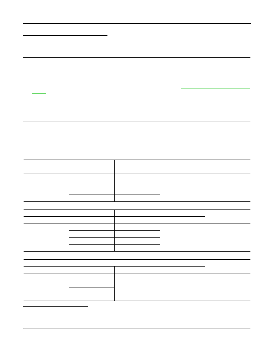
Check continuity between terminals. (Also check continuity when steering wheel is turned right and left
and when sensor harness inside the wheel house is moved.)

Measurement terminal for power supply circuit

Measurement terminal for signal circuit

Measurement terminal for ground circuit

Is the inspection result normal?

YES

>> GO TO 5.

NO

>> Repair or replace malfunctioning components.

5.

CHECK WHEEL SENSOR POWER SUPPLY CIRCUIT

1.

Disconnect malfunctioning wheel sensor connector.

2.

Turn ignition switch ON.

ABS actuator and electric unit (control unit)

Wheel sensor

Continuity

Connector

Terminal

Connector

Terminal

E41

9

E27 (Front RH)

1

Existed

26

E60 (Front LH)

7

B33 (Rear RH)

6

B34 (Rear LH)

ABS actuator and electric unit (control unit)

Wheel sensor

Continuity

Connector

Terminal

Connector

Terminal

E41

10

E27 (Front RH)

2

Existed

5

E60 (Front LH)

29

B33 (Rear RH)

27

B34 (Rear LH)

ABS actuator and electric unit (control unit)

Continuity

Connector

Terminal

Connector

Terminal

E41

9, 10

E41

1, 4

Not existed

26, 5

7, 29

6, 27

C1105, C1106, C1107, C1108 WHEEL SENSOR-2

BRC-35

< COMPONENT DIAGNOSIS >

[VDC/TCS/ABS]

C

D

E

G

H

I

J

K

L

M

A

B

BRC

N

O

P

3.

Check voltage between wheel sensor harness connector power supply terminal and ground.

Is the inspection result normal?

YES

>> Replace applicable wheel sensor.

NO

>> Replace ABS actuator and electric unit (control unit).

Component Inspection

INFOID:0000000000958526

1.

CHECK DATA MONITOR

On “DATA MONITOR”, select “FR LH SENSOR”, “FR RH SENSOR”, “RR LH SENSOR”, and “RR RH SEN-
SOR”, and check the vehicle speed.

Is the inspection result normal?

YES

>> INSPECTION END

NO

>> Go to diagnosis procedure. Refer to 

BRC-43, "Diagnosis Procedure"

.

Special Repair Requirement

INFOID:0000000000958527

1.

ADJUSTMENT OF STEERING ANGLE SENSOR NEUTRAL POSITION

Always perform the neutral position adjustment for the steering angle sensor, when replacing the ABS actua-
tor and electric unit (control unit). Refer to 

BRC-8, "ADJUSTMENT OF STEERING ANGLE SENSOR NEU-

TRAL POSITION : Description"

.

>> END

Wheel sensor

Voltage

Connector

Terminal

E27 (Front RH)

1

Ground

8 V or more

E60 (Front LH)

B33 (Rear RH)

B34 (Rear LH)

Wheel sensor

Vehicle speed (DATA MONITOR)

FR LH SENSOR

Nearly matches the speedometer dis-
play (

±

10% or less)

FR RH SENSOR

RR LH SENSOR

RR RH SENSOR

BRC-36

< COMPONENT DIAGNOSIS >

[VDC/TCS/ABS]

C1109 POWER AND GROUND SYSTEM

C1109 POWER AND GROUND SYSTEM

Description

INFOID:0000000000958528

Supplies electric power to the ABS actuator and electric unit (control unit).

DTC Logic

INFOID:0000000000958529

DTC DETECTION LOGIC

DTC CONFIRMATION PROCEDURE

1.

CHECK SELF-DIAGNOSIS RESULTS

Check the self-diagnosis results.

Is above displayed on the self-diagnosis display?

YES

>> Proceed to diagnosis procedure. Refer to 

BRC-36, "Diagnosis Procedure"

.

NO

>> INSPECTION END

Diagnosis Procedure

INFOID:0000000000958530

INSPECTION PROCEDURE

1.

CHECK CONNECTOR

1.

Turn ignition switch OFF.

2.

Disconnect ABS actuator and electric unit (control unit) connector.

3.

Check terminal for deformation, disconnection, looseness, and so on. If any malfunction is found, repair or
replace terminal.

4.

Reconnect connectors and then perform the self-diagnosis. Refer to 

BRC-26, "CONSULT-III Function

(ABS)"

.

Is any item indicated on the self-diagnosis display?

YES

>> GO TO 2.

NO

>> Poor connection of connector terminal. Repair or replace connector.

2.

CHECK ABS ACTUATOR AND ELECTRIC UNIT (CONTROL UNIT) POWER SUPPLY CIRCUIT AND

GROUND CIRCUIT

1.

Turn ignition switch OFF.

2.

Disconnect ABS actuator and electric unit (control unit) connector.

3.

Turn ignition switch ON or OFF and check voltage between ABS actuator and electric unit (control unit)
harness connector terminal and ground.

4.

Turn ignition switch OFF.

5.

Check continuity between ABS actuator and electric unit (control unit) harness connector terminals and
ground.

DTC

Display item

Malfunction detected condition

Possible cause

C1109

BATTERY VOLTAGE
[ABNORMAL]

When the ABS actuator and electric unit (control unit) 
power supply voltage is lower than normal.

• Harness or connector
• ABS actuator and electric unit 

(control unit)

Self-diagnosis results

BATTERY VOLTAGE [ABNORMAL]

ABS actuator and electric unit (control unit)

Condition

Voltage

Connector

Terminal

E41

28

Ground

Ignition switch: ON

Battery voltage

Ignition switch: OFF

Approx. 0 V

C1109 POWER AND GROUND SYSTEM

BRC-37

< COMPONENT DIAGNOSIS >

[VDC/TCS/ABS]

C

D

E

G

H

I

J

K

L

M

A

B

BRC

N

O

P

Is the inspection result normal?

YES

>> Check battery for terminal looseness, low voltage, etc. If any malfunction is found, repair malfunc-

tioning parts.

NO

>> Repair or replace malfunctioning components.

Special Repair Requirement

INFOID:0000000000958531

1.

ADJUSTMENT OF STEERING ANGLE SENSOR NEUTRAL POSITION

Always perform the neutral position adjustment for the steering angle sensor, when replacing the ABS actua-
tor and electric unit (control unit). Refer to 

BRC-8, "ADJUSTMENT OF STEERING ANGLE SENSOR NEU-

TRAL POSITION : Description"

.

>> END

ABS actuator and electric unit (control unit)

Continuity

Connector

Terminal

E41

1, 4

Ground

Existed


Content   ..  238  239  240  241   ..