Infiniti G35 (V35) Sedan. Manual - part 198
BCS
SIGNAL BUFFER SYSTEM
BCS-9
< FUNCTION DIAGNOSIS >
C
D
E
F
G
H
I
J
K
L
B
A
O
P
N
SIGNAL BUFFER SYSTEM
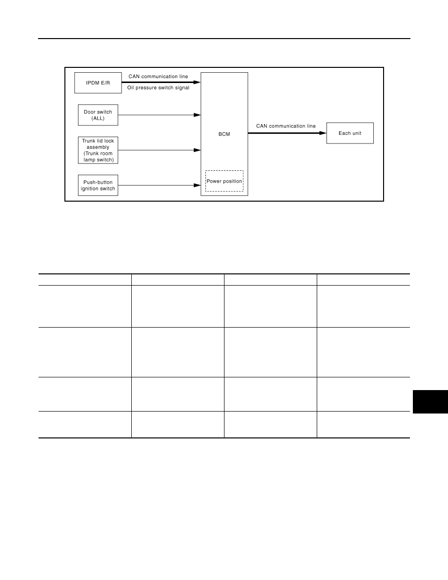
System Diagram
INFOID:0000000000963866
System Description
INFOID:0000000000963867
OUTLINE
BCM has the signal transmission function that outputs/transmits each input/received signal to each unit.
Signal transmission function list
JPMIA0070GB
Signal name
Input
Output
Description
• Ignition switch ON signal
• Ignition switch signal
Push-button ignition switch
(push switch)
• IPDM E/R (CAN)
• Driver seat control unit (CAN)
Inputs the push-button ignition
switch (push switch) signal and
transmits the ignition switch sta-
tus judged with BCM via CAN
communication.
Door switch signal
Any door switch
• Combination meter (via uni-
fied meter and A/C amp.)
(CAN)
• IPDM E/R (CAN)
• Driver seat control unit (CAN)
• AV control unit (CAN)
Inputs the door switch signal
and transmits it via CAN com-
munication.
Trunk switch signal
Trunk room lamp switch
• Combination meter (via uni-
fied meter and A/C amp.)
(CAN)
• AV control unit (CAN)
Inputs the trunk room lamp
switch signal and transmits the
trunk switch signal via CAN
communication.
Oil pressure switch signal
IPDM E/R (CAN)
Combination meter (via unified
meter and A/C amp.) (CAN)
Transmits the received oil pres-
sure switch signal via CAN
communication.