Infiniti G35 (V35) Sedan. Manual - part 197
BCS
COMBINATION SWITCH READING SYSTEM
BCS-5
< FUNCTION DIAGNOSIS >
C
D
E
F
G
H
I
J
K
L
B
A
O
P
N
COMBINATION SWITCH READING SYSTEM
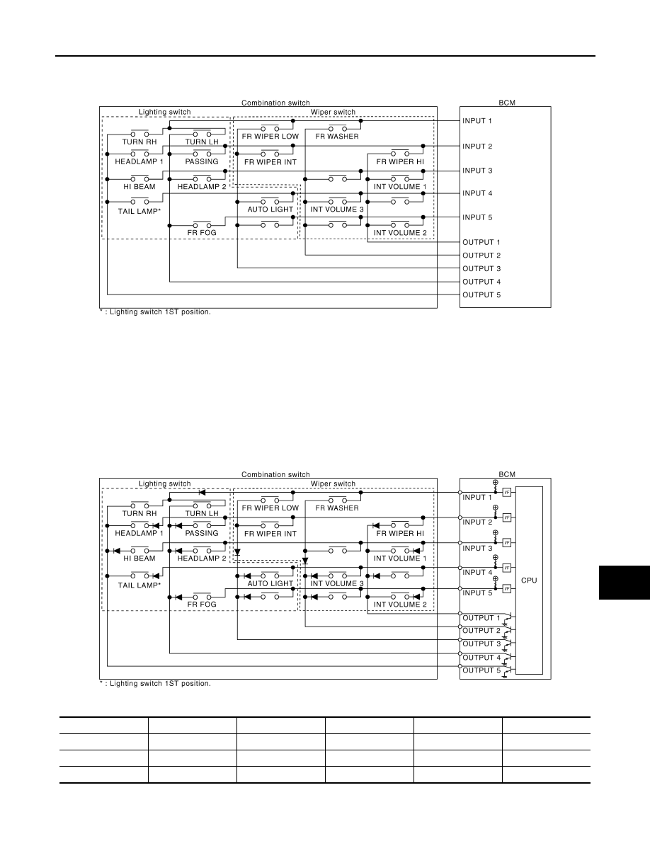
System Diagram
INFOID:0000000000963863
System Description
INFOID:0000000000963864
OUTLINE
• BCM reads the status of the combination switch (light, turn signal, wiper and washer) and recognizes the
status of each switch.
• BCM is a combination of 5 output terminals (OUTPUT 1 - 5) and 5 input terminals (INPUT 1 - 5). It reads a
maximum of 20 switch status.
COMBINATION SWITCH MATRIX
Combination switch circuit
Combination switch INPUT-OUTPUT system list
JPMIA0083GB
System
OUTPUT 1
OUTPUT 2
OUTPUT 3
OUTPUT 4
OUTPUT 5
INPUT 1
—
FR WASHER
FR WIPER LOW
TURN LH
TURN RH
INPUT 2
FR WIPER HI
—
FR WIPER INT
PASSING
HEADLAMP 1
INPUT 3
INT VOLUME 1
—
—
HEADLAMP 2
HI BEAM
JPMIA0066GB