Infiniti G35 (V35) Sedan. Manual - part 142
AV-340
< FUNCTION DIAGNOSIS >
[BOSE AUDIO WITH NAVIGATION]
DIAGNOSIS SYSTEM (AV CONTROL UNIT)
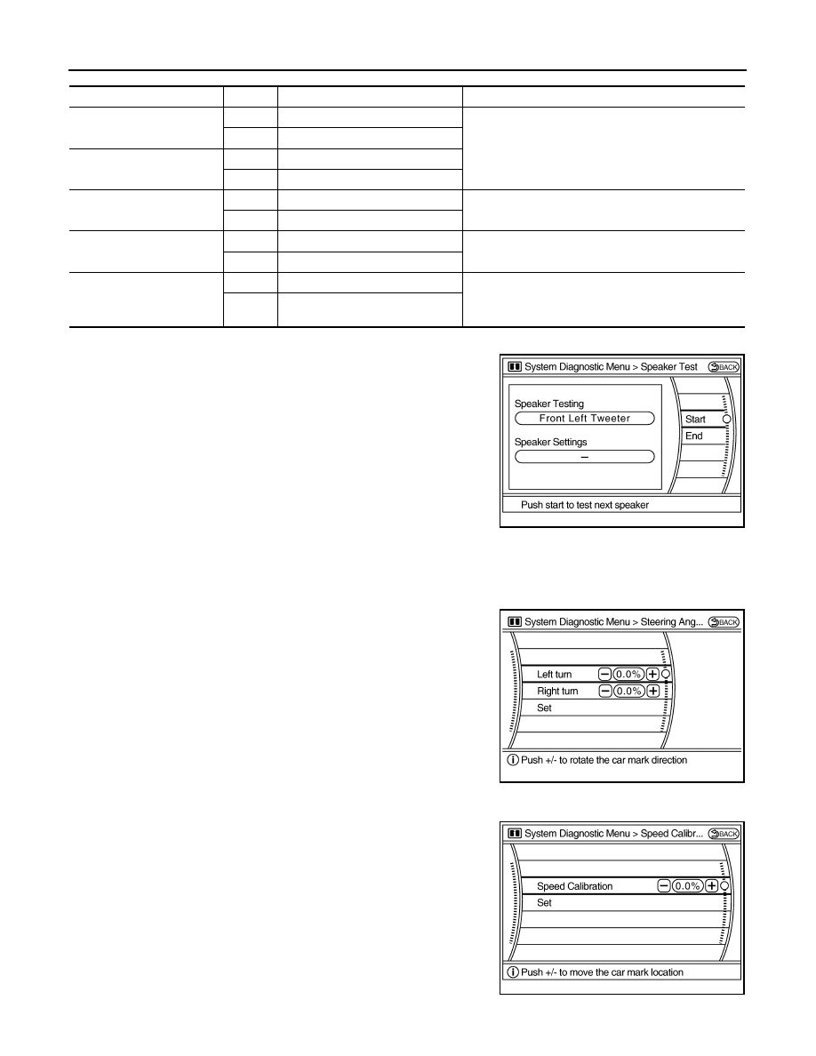
Speaker Test
Select “SPEAKER DIAGNOSIS” to display the Speaker Diagnosis
screen. Press “START and NEXT” to generate a test tone in a
speaker. Press “Start” to generate a test tone in the next speaker.
Press “End” to stop the test tones.
NOTE:
The frequency of test tone emitted from each speaker is as follows.
Climate Control
Refer to “HEATER & AIR CONDITIONING CONTROL SYSTEM” for details.
Navigation
STEERING ANGLE ADJUSTMENT
The steering angle output value detected with the gyroscope is
adjusted.
SPEED CALIBRATION
During normal driving, distance error caused by tire wear and tire
pressure change is automatically adjusted for by the automatic dis-
tance correction function. This function, on the other hand, is for
immediate adjustment, in cases such as driving with tire chain fitted
on tires.
Diagnosis item
Display
Vehicle status
Remarks
Vehicle speed
ON
Vehicle speed > 0 km/h (0 MPH)
Changes in indication may be delayed by approximate-
ly 1.5 seconds. This is normal.
OFF
Vehicle speed = 0 km/h (0 MPH)
Parking brake
ON
Parking brake is applied.
OFF
Parking brake is released.
Lights
ON
Light switch ON
Block the light beam from the auto light optical sensor.
OFF
Light switch OFF
Ignition
ON
Ignition switch ON
—
OFF
Ignition switch in ACC position
Reverse
ON
Selector lever in R position
Changes in indication may be delayed by approximate-
ly 1.5 seconds. This is normal.
OFF
Selector lever in any position other
than R
Tweeter
: 3 kHz
Front door speaker
: 300 Hz
Rear door speaker
: 1 kHz
JSNIA0076GB
JSNIA0077GB
JSNIA0078GB