Content .. 1390 1391 1392 1393 ..
Infiniti G35 (V35) Sedan. Manual - part 1392
TM-260
< ON-VEHICLE REPAIR >
[5AT: RE5R05A]
REAR OIL SEAL
REAR OIL SEAL
2WD
2WD : Exploded View
INFOID:0000000000957161
2WD : Removal and Installation
INFOID:0000000000957162
REMOVAL
1.
Remove exhaust front tube and center muffler with power tool. Refer to
.
2.
Remove rear propeller shaft. Refer to
.
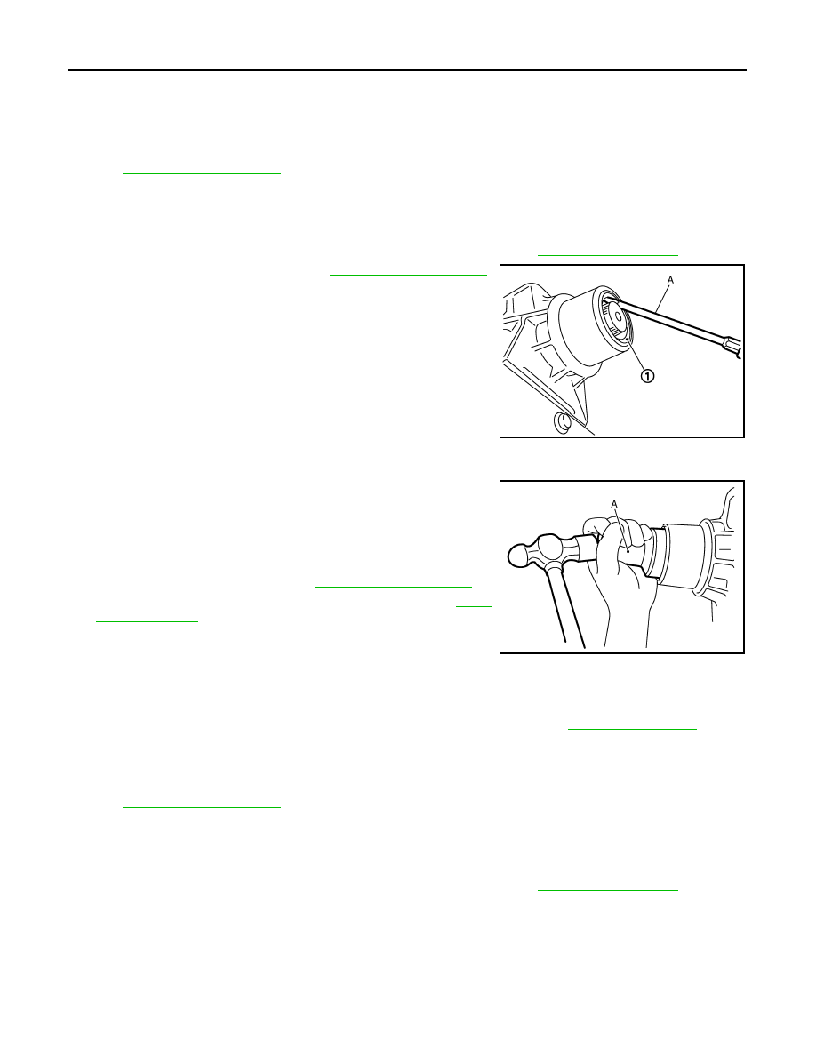
3.
Remove rear oil seal (1) using a flat-bladed screwdriver (A).
CAUTION:
Be careful not to scratch rear extension assembly.
INSTALLATION
1.
As shown in the figure, use the drift [SST: ST33400001 (J-
26082)] (A) to drive rear oil seal into rear extension assembly
until it is flush.
CAUTION:
• Do not reuse rear oil seal.
• Apply ATF to rear oil seal.
2.
Install rear propeller shaft. Refer to
.
3.
Install exhaust front tube and center muffler. Refer to
2WD : Inspection
INFOID:0000000000957163
INSPECTION AFTER INSTALLATION
After completing installation, check A/T fluid leakage and A/T fluid level. Refer to
.
AWD
AWD : Exploded View
INFOID:0000000000957164
(AWD).
AWD : Removal and Installation
INFOID:0000000000957165
REMOVAL
1.
Remove exhaust front tube and center muffler with power tool. Refer to
.
JPDIA0037ZZ
JPDIA0039ZZ