Content .. 1383 1384 1385 1386 ..
Infiniti G35 (V35) Sedan. Manual - part 1385
TM-232
< ON-VEHICLE REPAIR >
[5AT: RE5R05A]
CONTROL DEVICE
ON-VEHICLE REPAIR
CONTROL DEVICE
2WD
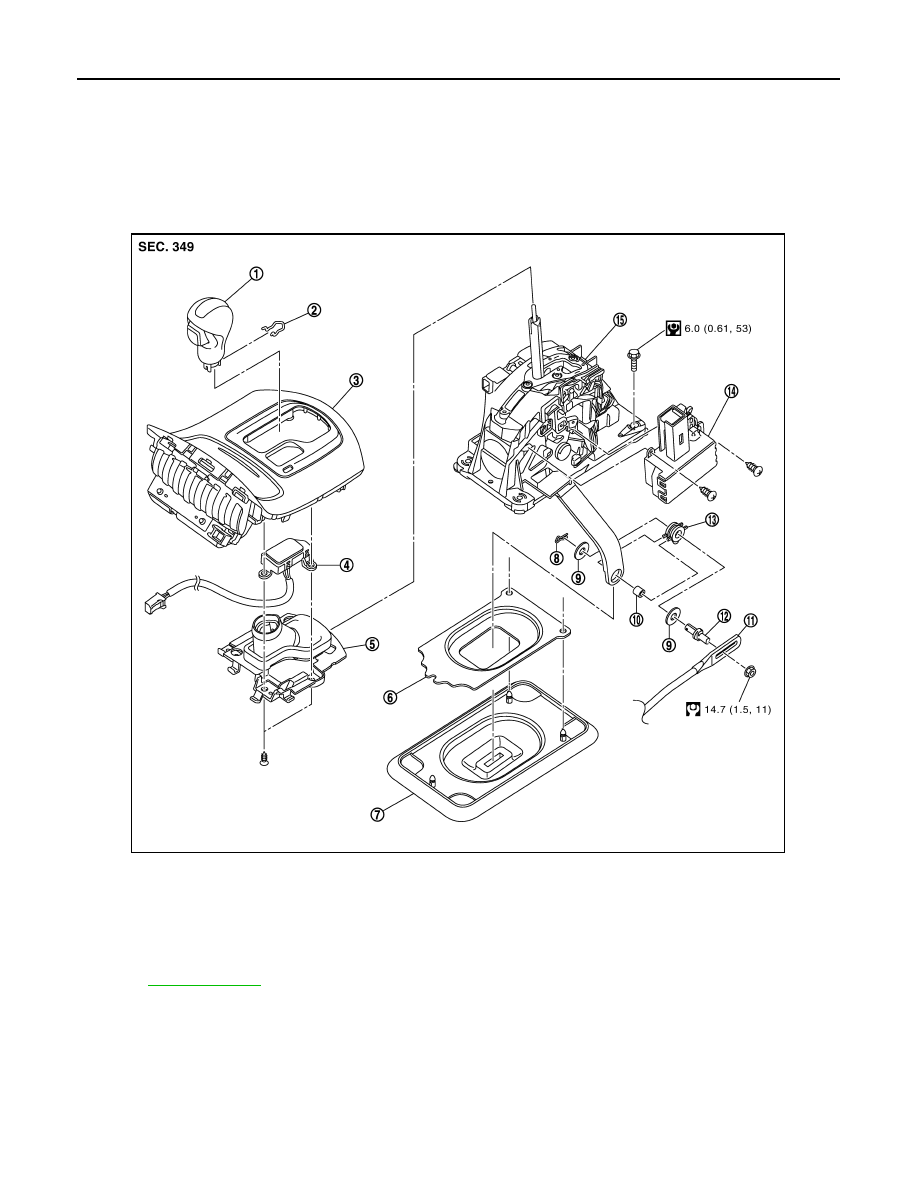
2WD : Exploded View
INFOID:0000000000957138
2WD : Removal and Installation
INFOID:0000000000957139
REMOVAL
1.
Disconnect lower lever of control device and control rod.
2.
Move selector lever to “N” position.
1.
Selector lever knob
2.
Lock pin
3.
Console finisher
4.
Selector lever position indicator
5.
Insert finisher
6.
Dust cover plate
7.
Dust cover
8.
Snap pin
9.
Plain washer
10.
Collar
11.
Control rod
12.
Pivot pin
13.
Insulator
14.
Shift lock unit
15.
Control device assembly
Refer to
for symbols in the figure.
JPDIA0001GB