Content .. 1337 1338 1339 1340 ..
Infiniti G35 (V35) Sedan. Manual - part 1339
TM-48
< DISASSEMBLY AND ASSEMBLY >
[6MT: FS6R31A]
TRANSMISSION ASSEMBLY
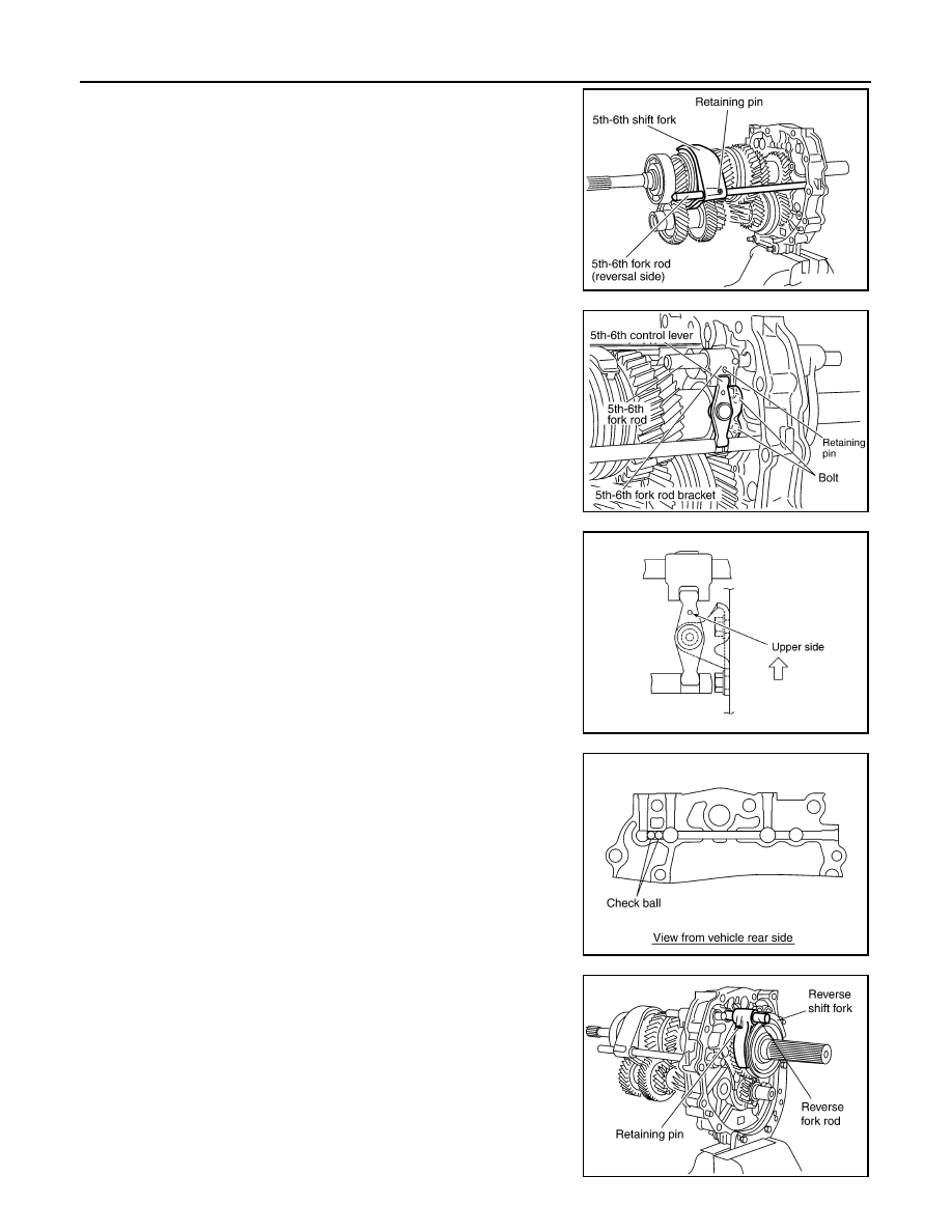
1.
Install 5th-6th shift fork to 5th-6th coupling sleeve.
2.
Install 5th-6th fork rod (reversal side) to 5th-6th shift fork.
3.
Using a pin punch to tap retaining pin into 5th-6th shift fork.
CAUTION:
Do not reuse retaining pin.
4.
Install 5th-6th fork rod to adapter plate.
5.
Install 5th-6th fork rod bracket to 5th-6th fork rod.
6.
Using a pin punch to tap retaining pin into 5th-6th fork rod
bracket.
CAUTION:
Do not reuse retaining pin.
7.
Install 5th-6th control lever to adapter plate and then tighten
mounting bolts to the specified torque.
CAUTION:
Set the projection upward.
8.
Apply recommended grease check balls and then install check
balls to adapter plate.
9.
Install reverse shift fork to reverse coupling sleeve.
10. Install reverse fork rod to reverse shift fork.
11. Using a pin punch to tap retaining pin into reverse shift fork.
CAUTION:
Do not reuse retaining pin.
PCIB0412E
PCIB0238E
PCIB0172E
PCIB0148E
SCIA1447E