Content .. 1331 1332 1333 1334 ..
Infiniti G35 (V35) Sedan. Manual - part 1333
TM-24
< ON-VEHICLE REPAIR >
[6MT: FS6R31A]
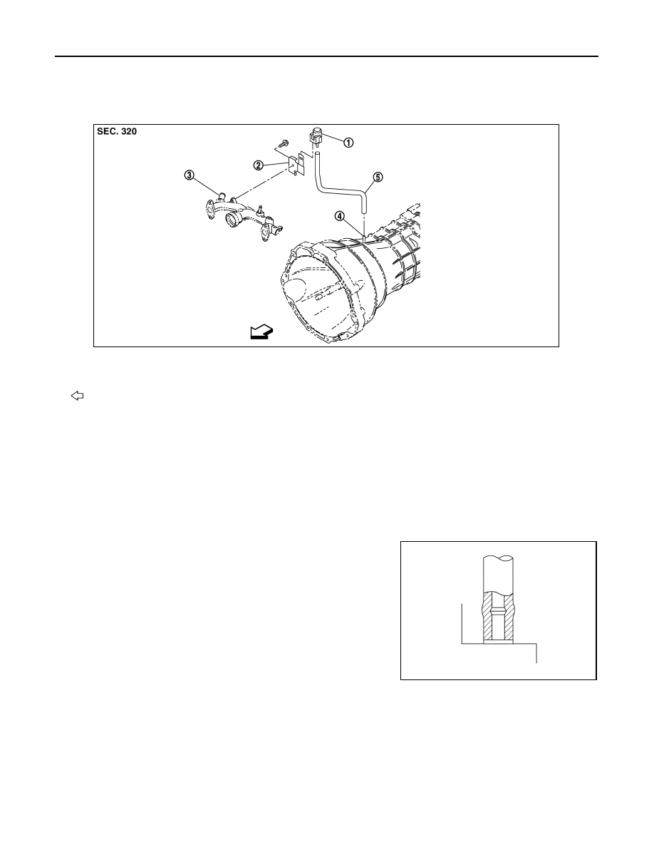
AIR BREATHER HOSE
AIR BREATHER HOSE
Exploded View
INFOID:0000000000956964
Removal and Installation
INFOID:0000000000956965
REMOVAL
Refer to the figure for removal procedure.
INSTALLATION
Refer to the figure for installation procedure.
CAUTION:
• Make sure there are no pinched or restricted areas on the air breather hose caused by bending or
winding when installing it.
• Be sure to insert air breather hose into breather tube until
hose end reaches the tube's base.
• Be sure to insert air breather hose into breather until hose
end reaches the breather's base.
1.
Breather
2.
Bracket
3.
Water outlet (rear)
4.
Breather tube
5.
Air breather hose
: Vehicle front
JPDIC0011ZZ
SCIA2663J