Content .. 1330 1331 1332 1333 ..
Infiniti G35 (V35) Sedan. Manual - part 1332
TM-20
< ON-VEHICLE REPAIR >
[6MT: FS6R31A]
SHIFT CONTROL
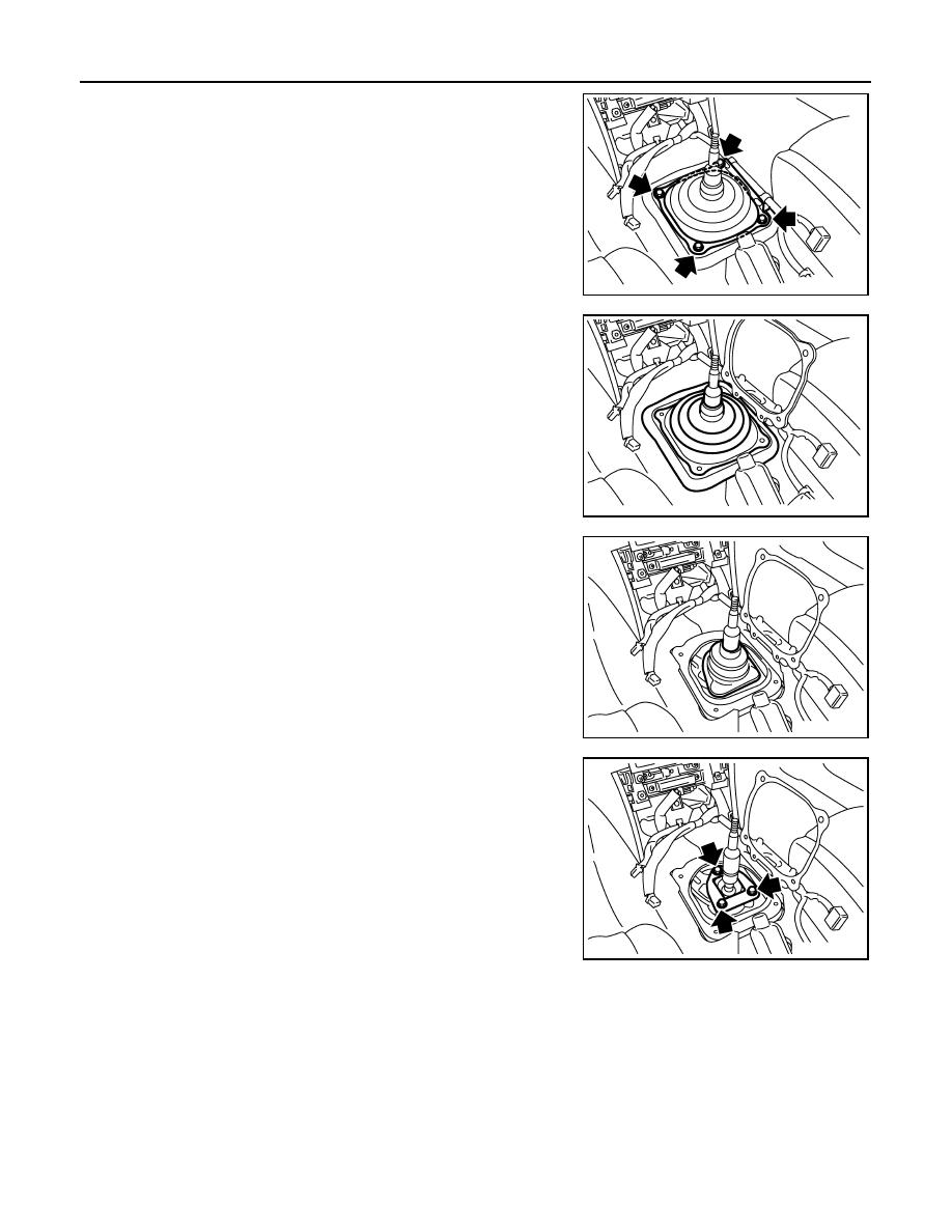
7.
Remove hole cover mounting bolts and then remove hole cover.
8.
Remove control lever boot B and hole insulator.
9.
Remove control lever boot A.
10. Remove guide plate mounting bolts and then remove control
lever assembly and control lever spring from control lever hous-
ing.
CAUTION:
Restrain guide plate while doing this because there is a
danger control lever assembly will fly out of control lever
housing.
INSTALLATION
1.
Set control lever spring, control lever assembly, and guide plate to control lever housing and then tempo-
rarily tightening guide plate mounting bolts.
CAUTION:
Restrain guide plate while doing this because there is a danger control lever assembly will fly out
of control lever housing.
JPDIC0006ZZ
JPDIC0007ZZ
JPDIC0008ZZ
JPDIC0009ZZ