Infiniti G35 (V35) Sedan. Manual - part 1331


  Index      Infiniti     Infiniti G35 (V35) Sedan - service repair manual 2007 year


Search            


Content   ..  1329  1330  1331  1332   ..


Infiniti G35 (V35) Sedan. Manual - part 1331


TM-16

< ON-VEHICLE MAINTENANCE >

[6MT: FS6R31A]

M/T OIL

ON-VEHICLE MAINTENANCE

M/T OIL

Exploded View

INFOID:0000000000956955

Refer to 

TM-30, "Exploded View"

.

Draining

INFOID:0000000000956956

1.

Start the engine and warm up the transmission unit sufficiently.

2.

After stopping engine, remove filler plug and drain plug to drain oil.

3.

Set a gasket on drain plug and install it to transmission. Tighten drain plug to the specified torque.

CAUTION:

Do not reuse gasket.

Refilling

INFOID:0000000000956957

1.

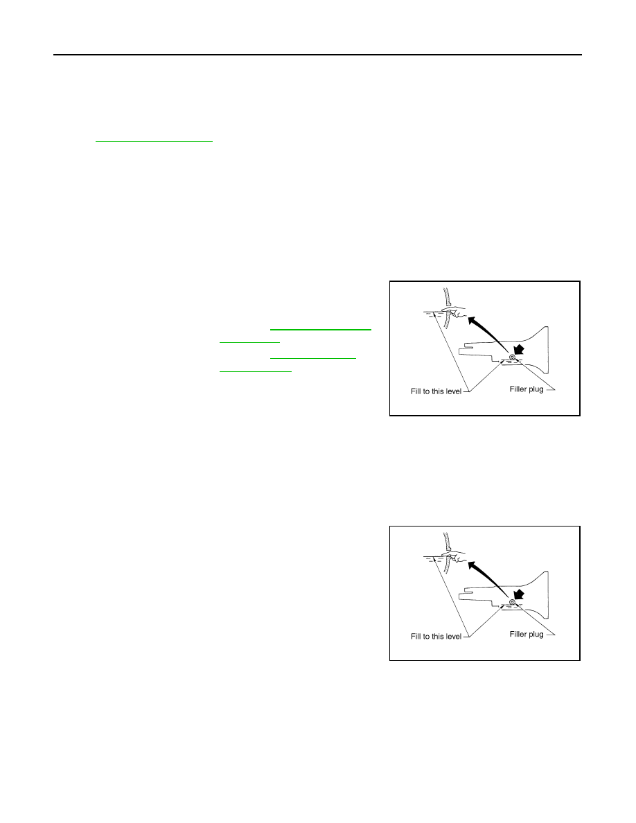
Fill new oil into the transmission to the level of the filler plug
mounting hole.

2.

After refilling oil, check oil level.

3.

Set a gasket on filler plug and then install it to transmission.
Tighten filler plug to the specified torque.

CAUTION:

Do not reuse gasket.

Inspection

INFOID:0000000000956958

LEAKAGE

• Check if oil is leaking from transmission or around it.

LEVEL

• Check oil level from filler plug mounting hole as shown in the fig-

ure.

CAUTION:

Never start engine while checking oil level.

• When screwing in filler plug, first screw into the transmission by

hand, then tighten to the specified torque.

CAUTION:

Do not reuse gasket.

Oil grade and viscosity

: Refer to 

MA-10, "Fluids and 

Lubricants"

.

Oil capacity

: Refer to 

TM-75, "General 

Specification"

.

PCIB0268E

PCIB0268E

REAR OIL SEAL

TM-17

< ON-VEHICLE REPAIR >

[6MT: FS6R31A]

C

E

F

G

H

I

J

K

L

M

A

B

TM

N

O

P

ON-VEHICLE REPAIR

REAR OIL SEAL

Exploded View

INFOID:0000000000956959

Refer to 

TM-30, "Exploded View"

.

Removal and Installation

INFOID:0000000000956960

REMOVAL

1.

Remove propeller shaft assembly. Refer to 

DLN-86, "Removal and Installation"

.

2.

Remove rear oil seal using a puller [SST: KV381054S0 (J-
34286)].

INSTALLATION

1.

Apply multi-purpose grease to lip of rear oil seal (1). Drive in rear
oil seal to rear extension using the drift (A) [SST: ST33400001
(J-26082)].

CAUTION:

• Do not reuse rear oil seal.
• When installing, do not incline rear oil seal.

2.

Install propeller shaft assembly. Refer to 

DLN-86, "Removal and

Installation"

.

CAUTION:

• If lubricant leak has occurred during the repair work,

check oil level after finishing work. Refer to 

TM-16,

"Inspection"

.

PCIB0194E

Dimension “H”

: 1.2 - 2.2 mm (0.047 - 0.087 in)

JPDIC0032ZZ

TM-18

< ON-VEHICLE REPAIR >

[6MT: FS6R31A]

SHIFT CONTROL

SHIFT CONTROL

Exploded View

INFOID:0000000000956961

Removal and Installation

INFOID:0000000000956962

REMOVAL

1.

Remove shift knob with the following procedure.

a.

Release metal clips on console finisher assembly. Refer to 

IP-12, "Removal and Installation"

.

1.

Shift knob

2.

Insulator

3.

Seat

4.

Console finisher assembly

5.

Felt

6.

Hole cover

7.

Control lever boot B

8.

Hole insulator

9.

Control lever boot A

10. Guide plate

11.

Control lever assembly

12. Control lever spring

13. Control lever housing

14. Control rod

: Apply multi-purpose grease.

: Apply Genuine Medium Strength Thread Locking Sealant or an equivalent. Refer to 

GI-15, "Recommended Chemical Prod-

ucts and Sealants"

.

Refer to 

GI-4, "Components"

 for symbols not described on the above.

JPDIC0001GB

SHIFT CONTROL

TM-19

< ON-VEHICLE REPAIR >

[6MT: FS6R31A]

C

E

F

G

H

I

J

K

L

M

A

B

TM

N

O

P

b.

Lift console finisher assembly and then set a suitable pliers to
control lever assembly.

CAUTION:

Put waste cloth (A) between a suitable pliers and control
lever assembly to avoid damaging control lever assembly. 

c.

Set a suitable pliers to shift knob.

CAUTION:

Put waste cloth (A) between a suitable pliers and shift knob
to avoid damaging shift knob.

d.

Keeping control lever assembly in place with a suitable pliers,
loosen shift knob with a suitable pliers.
NOTE:
Remove shift knob from control lever assembly keeping a suit-
able pliers in place because a certain power to turn shift knob is
still necessary even after adhesive is peeled.

e.

Remove shift knob from control lever assembly.

2.

Remove insulator and seat from control lever assembly.

3.

Remove console finisher assembly.

4.

Remove center console assembly. Refer to 

IP-12, "Removal and

Installation"

.

5.

Remove felt.

6.

Release boot from control lever housing. Then remove control
rod mounting bolt and then separate control lever assembly and
control rod.

JPDIC0002ZZ

JPDIC0003ZZ

JPDIC0004ZZ

JPDIC0005ZZ

SCIA2561J


Content   ..  1329  1330  1331  1332   ..