Content .. 1287 1288 1289 1290 ..
Infiniti G35 (V35) Sedan. Manual - part 1289
STC-46
< FUNCTION DIAGNOSIS >
[WITH 4WAS]
DIAGNOSIS SYSTEM (4WAS MAIN CONTROL UNIT)
• The communication status and the number of errors of 4WAS main control unit, ECM, ABS actuator and
electric unit (control unit), 4WAS front control unit and the steering angle sensor are indicated.
• Error counter displays OK if any malfunction is not detected in the past. If the malfunction is detected, it dis-
plays 0. When turning the ignition switch ON, if it is normal, it displays 1. The upper limit of the counter is 39.
ACTIVE TEST MODE
Description
• 4WAS rear actuator assembly activation is checked according to the control signal from CONSULT-III.
• The control signal forcibly activates (ON/OFF) 4WAS rear assembly, performs the self-diagnosis and checks
each sensor in “SELF DIAGNOSTIC MODE”.
CAUTION:
Perform the active test while the vehicle is stopped.
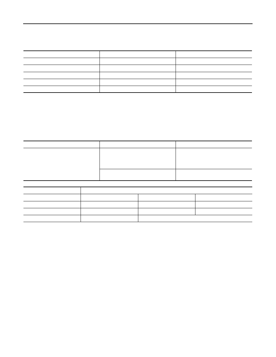
Standard value
Item
PRSNT
PAST
TRANSMIT DIAG
OK / UNKWN
OK / 0 – 39
ECM
OK / UNKWN
OK / 0 – 39
VDC/TCS/ABS
OK / UNKWN
OK / 0 – 39
STRG
OK / UNKWN
OK / 0 – 39
4WAS
OK / UNKWN
OK / 0 – 39
Select test item
Control signal
Remarks
SELF DIAGNOSTIC MODE
ON
CAUTION:
Perform the active test while the vehicle
is stopped.
4WAS rear actuator assembly activates. It
activates in the same direction as the steer-
ing angle by inputting the steering angle.
OFF
4WAS rear actuator assembly stops the ac-
tivation.
Monitor item
Active test “ON”
STEERING ANG
0
°
(Neutral)
R 90
°
L 90
°
RR ST ANG-MAI
2.4 V
Approx. 4.4 V
Approx. 0.4 V
RR ST ANG-SUB
2.4 V
Approx. 4.4 V
Approx. 0.4 V
MOTOR CURRENT
No output (Approx. 0 A)
Output (change)