Content .. 1279 1280 1281 1282 ..
Infiniti G35 (V35) Sedan. Manual - part 1281
STC-14
< COMPONENT DIAGNOSIS >
[WITHOUT 4WAS]
ENGINE SPEED SIGNAL CIRCUIT
NO
>> Replace ECM. Refer to
EC-15, "ADDITIONAL SERVICE WHEN REPLACING CONTROL UNIT :
.
4.
CHECK ENGINE SPEED SIGNAL (2)
1.
Turn the ignition switch OFF.
2.
Connect power steering control unit harness connector.
3.
Check signal between power steering control unit harness connector and ground with oscilloscope.
Also check harness for short to ground and short to power.
Is the inspection result normal?
YES
>> GO TO 5.
NO
>> Replace power steering control unit. Refer to
5.
CHECK TERMINALS AND HARNESS CONNECTORS
• Check power steering control unit pin terminals for damage or loose connection with harness connector.
• Check ECM pin terminals for damage or loose connection with harness connector.
Is the inspection result normal?
YES
>> INSPECTION END
NO
>> Repair or replace damaged parts.
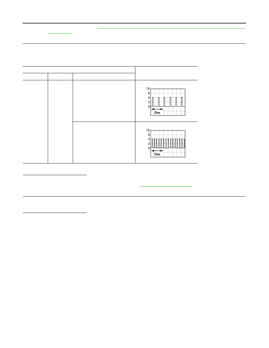
Power steering control unit
Value (Approx.)
Connector
Terminal
Condition
M108
10 – Ground
Engine speed: At idle
(Warm-up condition)
Engine speed: Approx. 2,000 rpm
(Warm-up condition)
PBIA3654J
PBIA3655J