Infiniti G35 (V35) Sedan. Manual - part 1273


  Index      Infiniti     Infiniti G35 (V35) Sedan - service repair manual 2007 year


Search            


Content   ..  1271  1272  1273  1274   ..


Infiniti G35 (V35) Sedan. Manual - part 1273


ST-42

< ON-VEHICLE REPAIR >

STEERING GEAR AND LINKAGE

e.

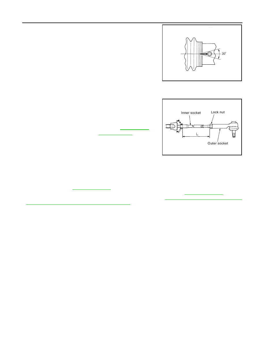
Bent cut end of the wire toward rack axial as shown in the figure
after twisting the wire 4 to 4.5 turns so that cut end does not con-
tact with boot.

CAUTION:

Keep gap from cylinder tube 5 mm (0.20 in) or more.

19. Install cylinder tubes to gear housing assembly.
20. Install low pressure piping.

21. Adjust inner socket to standard length “L”, and then tighten lock

nut to the specified torque. Check length “L” again after tighten-
ing lock nut.

CAUTION:

Adjust toe-in after this procedure. Length achieved after
toe-in adjustment is not necessary the above value.

AWD : Inspection

INFOID:0000000000958681

INSPECTION AFTER INSTALLATION

• Check if steering wheel turns smoothly when it is turned several times fully to the end of the left and right.
• Check the steering wheel play, neutral position steering wheel, steering wheel turning force, and front wheel

turning angle. Refer to 

ST-12, "Inspection"

.

• Check the fluid level, fluid leakage, and air bleeding hydraulic system. Refer to 

ST-10, "Inspection"

.

• Perform 4WAS front actuator neutral position adjustment. Refer to 

STC-27, "4WAS FRONT ACTUATOR

NEUTRAL POSITION ADJUSTMENT : Description"

.

INSPECTION AFTER DISASSEMBLY

Boot

• Check boot for cracks, and replace it if a malfunction is detected.

Rack Assembly

• Check rack for damage or wear, and replace it if a malfunction is detected.

Gear-Sub Assembly

• Check gear-sub assembly for damage or wear, and replace it if a malfunction is detected.
• Rotate gear-sub assembly and check for torque variation or rattle, and replace it if a malfunction is detected.

Gear Housing Assembly

• Check gear housing assembly for damage and scratches (inner wall). Replace if there are.

Outer Socket and Inner Socket

• Check the following items and replace the component if it does not meet the standard.

BALL JOINT SWINGING TORQUE

STC0124D

Standard

Inner socket length “L”

: Refer to 

ST-60, "Inner 

Socket Length"

.

SGIA0167E

STEERING GEAR AND LINKAGE

ST-43

< ON-VEHICLE REPAIR >

C

D

E

F

H

I

J

K

L

M

A

B

ST

N

O

P

• Hook a spring balance at the point shown in the figure and pull the

spring balance. Make sure that the spring balance reads the spec-
ified value when ball stud and inner socket start to move. Replace
outer socket and inner socket if they are outside the standard.

BALL JOINT ROTATING TORQUE

• Make sure that the reading is within the following specified range

using preload gauge (A) [SST: ST3127S000 (J-25765-A)]. Replace
outer socket if the reading is outside the specified value.

BALL JOINT AXIAL END PLAY

• Apply an axial load of 490 N (50 kg, 110 lb) to ball stud. Using a

dial gauge, measure amount of stud movement, and then make
sure that the value is within the following specified range. Replace
outer socket (1) and inner socket (2) if the measured value is out-
side the standard.

Standard for outer socket

(Measuring point: Stud cotter pin mounting hole)

Spring balance measure-
ment

: Refer to 

ST-59, "Socket 

Swing Force and Rotating 
Torque"

.

Standard for inner socket

(Measuring point: “*” mark shown in the figure)

Spring balance measure-
ment

: Refer to 

ST-59, "Socket 

Swing Force and Rotating 
Torque"

.

Standard

Outer socket rotating 
torque

: Refer to 

ST-59, "Socket 

Swing Force and Rotating 
Torque"

.

SGIA0896E

SGIA1382E

Standard

Outer socket

Refer to 

ST-60, "Socket Axial 

End Play"

.

Inner socket

: Refer to 

ST-60, "Socket Axial 

End Play"

.

JSGIA0109ZZ

ST-44

< ON-VEHICLE REPAIR >

POWER STEERING OIL PUMP

POWER STEERING OIL PUMP

WITHOUT 4WAS

WITHOUT 4WAS : Exploded View

INFOID:0000000000958682

REMOVAL AND INSTALLATION

DISASSEMBLY AND ASSEMBLY

1.

Power steering oil pump

2.

Bracket

: Vehicle front

Refer to 

GI-4, "Components"

 for symbols in the figure.

JSGIA0046GB

1.

Pulley

2.

Oil seal

3.

Bracket

4.

Body assembly

5.

Suction pipe

6.

O-ring 

JSGIA0103GB

POWER STEERING OIL PUMP

ST-45

< ON-VEHICLE REPAIR >

C

D

E

F

H

I

J

K

L

M

A

B

ST

N

O

P

WITHOUT 4WAS : Removal and Installation

INFOID:0000000000958683

REMOVAL

1.

Drain power steering fluid from reservoir tank.

2.

Remove the right half of the air cleaner and the right half of the air duct. Refer to 

EM-25, "Exploded View"

.

3.

Loosen drive belt. Refer to 

EM-12, "Removal and Installation"

.

4.

Remove drive belt from oil pump pulley.

5.

Remove copper washers and eye bolt (drain fluid from their pipings).

6.

Remove suction hose (drain fluid from their pipings).

7.

Remove oil pump mounting bolts, and then remove oil pump.

INSTALLATION

Note the following, and install in the reverse order of removal.
• When installing suction hoses (1), refer to the figure.

CAUTION:

• Never apply fluid to the hose (1) and tube (2).
• Insert hose securely until it contacts spool (A) of tube.
• Install clamp (3) to the hose at 3 – 8 mm (0.12 – 0.31 in) (L)

from the edge of the hose.

• When installing eye bolt (1) and copper washer (2) to oil pump (3),

refer to the figure.

CAUTION:

• Never reuse copper washer.
• Apply power steering fluid to around copper washer, then

install eye-bolt.

• Install eye-bolt with eye-joint (assembled to high pressure

hose) (B) protrusion (A) facing with pump side cutout, and
then tighten it to the specified torque after tightening by
hand. Refer to 

ST-55, "2WD : Exploded View"

 (2WD models),

ST-56, "AWD : Exploded View"

 (AWD models).

• Securely insert harness connector to pressure sensor.

• Adjust belt tension. Refer to 

EM-12, "Tension Adjustment"

.

• Check fluid level, fluid leakage and air bleeding hydraulic system after the installation. Refer to 

ST-10,

"Inspection"

.

WITHOUT 4WAS : Disassembly and Assembly

INFOID:0000000000958684

DISASSEMBLY

1.

Remove rear cover mounting bolts, and then remove rear cover from body assembly.

CAUTION:

7.

Flow control valve B assembly

8.

Flow control valve spring

9.

Flow control valve A

10. Dowel pin

11.

Front side plate

12. Vane

13. Rotor

14. Rotor snap ring

15. Cam ring 

16. Rear side plate

17. O-ring

18. Teflon ring

19. O-ring

20. Rear cover

21. Cartridge

A: Oil seal lip

: Apply power steering fluid.

: Apply multi-purpose grease.

Refer to 

GI-4, "Components"

 for symbols not described on the above.

JSGIA0118ZZ

SGIA1379E


Content   ..  1271  1272  1273  1274   ..