Infiniti G35 (V35) Sedan. Manual - part 1186


  Index      Infiniti     Infiniti G35 (V35) Sedan - service repair manual 2007 year


Search            


Content   ..  1184  1185  1186  1187   ..


Infiniti G35 (V35) Sedan. Manual - part 1186


B210E STARTER RELAY

SEC-99

< COMPONENT DIAGNOSIS >

[INTELLIGENT KEY SYSTEM]

C

D

E

F

G

H

I

J

L

M

A

B

SEC

N

O

P

3.

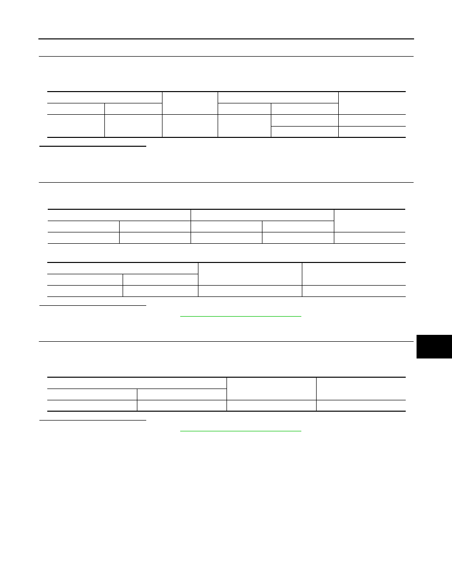
CHECK STARTER RELAY OUTPUT SIGNAL / M/T MODELS

1.

Turn ignition switch OFF.

2.

Disconnect BCM harness connector M121.

3.

Check voltage between BCM harness connector and ground.

Is the inspection result normal?

YES

>> GO TO 5.

NO

>> GO TO 4.

4.

CHECK STARTER RELAY OUTPUT SIGNAL CIRCUIT

1.

Disconnect IPDM E/R harness connector E6.

2.

Check continuity between BCM harness connector and IPDM E/R harness connector.

3.

Check continuity between BCM harness connector and ground.

Is the inspection result normal?

YES

>> Replace IPDM E/R. Refer to 

PCS-33, "Removal and Installation"

.

NO

>> Repair harness connector.

5.

CHECK STARTER RELAY POWER SUPPLY CIRCUIT

1.

Turn ignition switch OFF.

2.

Disconnect IPDM E/R harness connector E5.

3.

Check voltage between IPDM E/R harness connector and ground.

Is the inspection result normal?

YES

>> Replace IPDM E/R. Refer to 

PCS-33, "Removal and Installation"

.

NO

>> Check harness for open or short between IPDM E/R and battery.

BCM connector

Ground

Condition

Voltage (V)

Connector

Terminal

Ignition switch

Clutch pedal

M121

52

Ground

OFF

Not depressed

0

Depressed

Battery voltage

BCM

IPDM E/R

Continuity

Connector

Terminal

Connector

Terminal

M121

52

E6

46

Existed

BCM

Ground

Continuity

Connector

Terminal

M121

52

Ground

Not existed

IPDM E/R

Ground

Voltage (V)

Connector

Terminal

E5

36

Ground

Battery voltage

SEC-100

< COMPONENT DIAGNOSIS >

[INTELLIGENT KEY SYSTEM]

B210F PNP/CLUTCH INTERLOCK SWITCH

B210F PNP/CLUTCH INTERLOCK SWITCH

Description

INFOID:0000000000961449

IPDM E/R confirms the shift position with the following signals.
• Park/neutral position (PNP) switch (A/T models)
• Clutch inter lock switch (M/T models)
• Shift position signal from BCM (CAN)

DTC Logic

INFOID:0000000000961450

DTC DETECTION LOGIC

NOTE:
• If DTC B210F is displayed with DTC U1000, first perform the trouble diagnosis for DTC U1000. Refer to

SEC-35, "DTC Logic"

• If DTC B210F is displayed with DTC U1010, first perform the trouble diagnosis for DTC U1010. Refer to

SEC-36, "DTC Logic"

.

DTC CONFIRMATION PROCEDURE

1.

PERFORM DTC CONFIRMATION PROCEDURE

1.

Turn ignition switch ON under the following conditions and wait for at least 1 second.

-

A/T selector lever is in the P or N position

-

Do not depress the brake pedal

2.

Check “Self diagnostic result” with CONSULT-III. 

Is DTC detected?

YES

>> Go to 

EC-137, "Diagnosis Procedure"

.

NO

>> INSPECTION END

Diagnosis Procedure

INFOID:0000000000961451

1.

INSPECTION START

Check which type of transmission the vehicle is equipped with.

Which type of transmission

A/T

>> GO TO 2.

M/T

>> GO TO 5.

2.

CHECK DTC WITH BCM

Refer to 

SEC-167, "DTC Index"

.

Is the inspection result normal?

YES

>> GO TO 3.

NO

>> Repair or replace.

3.

CHECK PNP SWITCH INPUT SIGNAL

1.

Turn ignition switch OFF.

2.

Disconnect IPDM E/R harness connector E5.

3.

Turn ignition switch ON.

4.

Check voltage between IPDM E/R harness connector and ground under following condition.

DTC No.

Trouble diagnosis name

DTC detecting condition

Possible cause

B210F

INTER LOCK/PNP SW  
ON

IPDM E/R detects a mismatch between the signals 
below for 1 second or more.
• Clutch interlock input signal (M/T models)
• Shift NP switch input signal (A/T models)
• Shift position signal from BCM (CAN)

• Harness or connectors

[Park/neutral position (PNP) switch 
circuit is open or shorted (A/T mod-
els)] or (Clutch interlock switch cir-
cuit is open or shorted.)

• Clutch interlock switch (M/T mod-

els)

• Park/neutral position (PNP) switch 

(A/T models)

B210F PNP/CLUTCH INTERLOCK SWITCH

SEC-101

< COMPONENT DIAGNOSIS >

[INTELLIGENT KEY SYSTEM]

C

D

E

F

G

H

I

J

L

M

A

B

SEC

N

O

P

Is the inspection result normal?

YES

>> Replace IPDM E/R. Refer to 

PCS-33, "Removal and Installation"

.

NO

>> GO TO 4.

4.

CHECK PNP SWITCH CIRCUIT

1.

Turn ignition switch OFF.

2.

Disconnect A/T assembly harness connector.

3.

Check continuity between IPDM E/R harness connector and A/T assembly harness connector.

4.

Check continuity between IPDM E/R harness connector and ground.

Is the inspection result normal?

YES

>> GO TO 8.

NO

>> Repair harness or connector.

5.

CHECK CLUTCH INTERLOCK SWITCH INPUT SIGNAL (BCM)

1.

Turn ignition switch OFF.

2.

Disconnect BCM harness connector.

3.

Check voltage between BCM harness connector and ground.

Is the inspection result normal?

YES

>> GO TO 6.

NO

>> GO TO 11.

6.

CHECK CLUTCH INTERLOCK SWITCH INPUT SIGNAL

1.

Turn ignition switch OFF.

2.

Disconnect IPDM E/R harness connector E5.

3.

Check voltage between IPDM E/R harness connector and ground.

Is the inspection result normal?

YES

>> Replace IPDM E/R.

NO

>> GO TO 7.

7.

CHECK CLUTCH INTERLOCK SWITCH POWER SUPPLY

IPDM E/R

Ground

Condition

Voltage (V)

Connector

Terminal

E5

30

Ground

A/T selector lever

P or N

0

Other than above

Battery voltage

IPDM E/R

A/T assembly

Continuity

Connector

Terminal

Connector

Terminal

E5

30

F51

9

Existed

IPDM E/R

Ground

Continuity

Connector

Terminal

E5

30

Ground

Not existed

BCM

Ground

Condition

Voltage (V)

Connector

Terminal

M123

114

Ground

Clutch pedal

Not depressed

0

Depressed

Battery voltage

IPDM E/R

Ground

Condition

Voltage (V)

Connector

Terminal

E5

30

Ground

Clutch pedal

Not depressed

0

Depressed

Battery voltage

SEC-102

< COMPONENT DIAGNOSIS >

[INTELLIGENT KEY SYSTEM]

B210F PNP/CLUTCH INTERLOCK SWITCH

1.

Disconnect clutch interlock switch harness connector.

2.

Check voltage between clutch interlock switch harness connector and ground.

Is the inspection result normal?

YES

>> GO TO 8.

NO

>> Check harness for open or short between clutch interlock switch and fuse.

8.

CHECK CLUTCH INTERLOCK SWITCH CIRCUIT

1.

Check continuity between IPDM E/R harness connector and clutch interlock switch harness connector.

2.

Check continuity between IPDM E/R harness connector and ground.

Is the inspection result normal?

YES

>> GO TO 9.

NO

>> Repair harness or connector.

9.

CHECK CLUTCH INTERLOCK SWITCH

Refer to 

SEC-102, "Component Inspection"

.

Is the inspection result normal?

YES

>> GO TO 11.

NO

>> Replace clutch interlock switch.

10.

CHECK CLUTCH INTERLOCK SWITCH INPUT SIGNAL CIRCUIT

1.

Disconnect clutch interlock switch harness connector.

2.

Check continuity between BCM harness connector and clutch interlock switch harness connector.

3.

Check continuity between BCM harness connector and ground.

Is the inspection result normal?

YES

>> GO TO 11.

NO

>> Repair harness or connector.

11.

CHECK INTERMITTENT INCIDENT

Refer to 

GI-39, "Intermittent Incident"

.

>> INSPECTION END

Component Inspection

INFOID:0000000000961452

Clutch interlock switch

Ground

Voltage (V)

Connector

Terminal

E111

1

Ground

Battery voltage

IPDM E/R

Clutch interlock switch

Continuity

Connector

Terminal

Connector

Terminal

E5

30

E111

1

Existed

IPDM E/R

Ground

Continuity

Connector

Terminal

E5

30

Ground

Not existed

BCM

Clutch interlock switch

Continuity

Connector

Terminal

Connector

Terminal

M123

114

E111

2

Existed

BCM

Ground

Continuity

Connector

Terminal

M123

114

Ground

Not existed


Content   ..  1184  1185  1186  1187   ..