Infiniti G35 (V35) Sedan. Manual - part 1109


  Index      Infiniti     Infiniti G35 (V35) Sedan - service repair manual 2007 year


Search            


Content   ..  1107  1108  1109  1110   ..


Infiniti G35 (V35) Sedan. Manual - part 1109


RF-6

< FUNCTION DIAGNOSIS >

SUNROOF SYSTEM

ANTI-PINCH FUNCTION

The CPU of sunroof motor assembly monitors the sunroof motor operation and the sunroof position (fully-
closed or other) by the signals from sunroof motor.
When sunroof motor detects an interruption during the following slide close and tilt down operation, sunroof
switch controls the motor for open and the sunroof will operate until full up position (when tilt down operate) or
150 mm (5.91 in) or more in an open direction (when slide close operate):
• close operation and tilt down when ignition switch is in the “ON” position

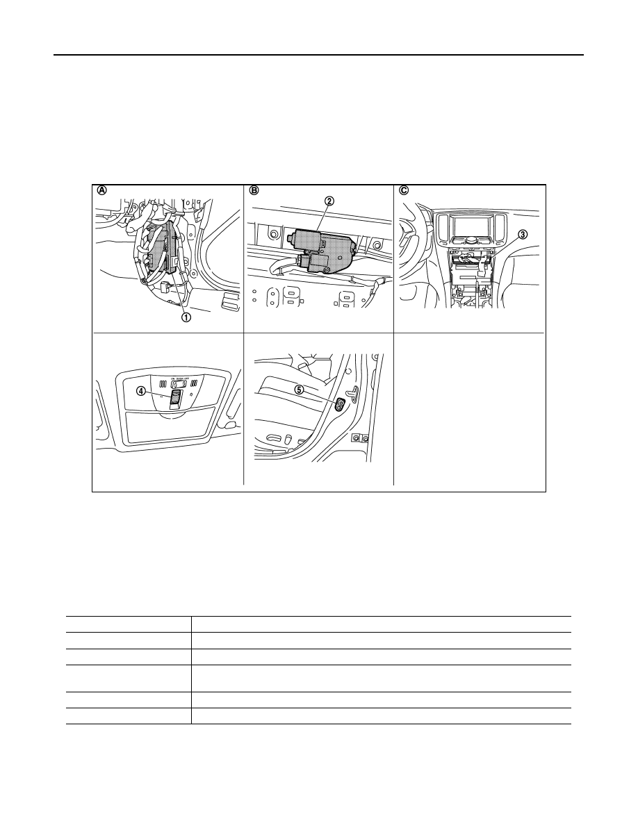
Component Parts Location

INFOID:0000000000961746

Component Description

INFOID:0000000000961747

JMKIA0031ZZ

1.

BCM  M118,M119,M121,M123

2.

Sunroof motor assembly  R4

3.

Unified meter and A/C amp. M66 

4.

Sunroof switch  R16

5.

Front door switch (driver side) B16

A.

View with dash side finisher RH re-
moved

B.

 View with headlining removed

C.

Behind cluster lid C 

Component

Function

BCM

Supplies the power supply to sunroof motor assembly.

Sunroof switch

Transmits tilt up/down & slides open/close operation signal to sunroof motor assembly.

Sunroof motor assembly

It is sunroof motor and CPU integrated type that enables tilt up/down & slide open/close by sun-
roof switch operation

Front door switch

Detects door open/ close condition and transmits to BCM.

Unified meter and A/C amp.

Transmits vehicle speed signal to sunroof motor assembly.

DIAGNOSIS SYSTEM (BCM)

RF-7

< FUNCTION DIAGNOSIS >

C

D

E

F

G

H

I

J

L

M

A

B

RF

N

O

P

DIAGNOSIS SYSTEM (BCM)

COMMON ITEM

COMMON ITEM : CONSULT-III Function (BCM - COMMON ITEM)

INFOID:0000000000961748

APPLICATION ITEM

CONSULT-III performs the following functions via CAN communication with BCM.

SYSTEM APPLICATION

BCM can perform the following functions for each system.
NOTE:
It can perform the diagnosis modes except the following for all sub system selection items.

*: This item is displayed, but is not used. 

RETAIND PWR

RETAIND PWR : CONSULT-III Function (BCM - RETAINED PWR)

INFOID:0000000000961749

Data monitor

Diagnosis mode

Function Description

WORK SUPPORT

Changes the setting for each system function.

SELF-DIAG RESULTS

Displays the diagnosis results judged by BCM. Refer to 

BCS-74, "DTC Index"

.

CAN DIAG SUPPORT MNTR

Monitors the reception status of CAN communication viewed from BCM.

DATA MONITOR

The BCM input/output signals are displayed.

ACTIVE TEST

The signals used to activate each device are forcibly supplied from BCM.

ECU IDENTIFICATION

The BCM part number is displayed.

CONFIGURATION

This function is not used even though it is displayed.

System

Sub system selection item

Diagnosis mode

WORK SUPPORT

DATA MONITOR

ACTIVE TEST

Door lock

DOOR LOCK

×

×

×

Rear window defogger

REAR DEFOGGER

×

×

Warning chime

BUZZER

×

×

Interior room lamp timer

INT LAMP

×

×

×

Exterior lamp

HEAD LAMP

×

×

×

Wiper and washer

WIPER

×

×

×

Turn signal and hazard warning lamps

FLASHER

×

×

×

Air conditioner*

AIR CONDITONER

×

Intelligent Key system

INTELLIGENT KEY

×

×

×

Combination switch

COMB SW

×

BCM

BCM

×

IVIS - NATS

IMMU

×

×

Interior room lamp battery saver

BATTERY SAVER

×

×

×

Trunk open

TRUNK

×

Vehicle security system

THEFT ALM

×

×

×

RAP system

RETAINED PWR

×

Signal buffer system

SIGNAL BUFFER

×

×

TPMS

TPMS (AIR PRESSURE MONI-
TOR)

×

×

×

RF-8

< FUNCTION DIAGNOSIS >

DIAGNOSIS SYSTEM (BCM)

Monitor Item

Description

DOOR SW-DR

Indicates [ON/OFF] condition of driver side door switch.

DOOR SW-AS

Indicates [ON/OFF] condition of passenger side door switch.

POWER SUPPLY AND GROUND CIRCUIT

RF-9

< COMPONENT DIAGNOSIS >

C

D

E

F

G

H

I

J

L

M

A

B

RF

N

O

P

COMPONENT DIAGNOSIS

POWER SUPPLY AND GROUND CIRCUIT

SUNROOF MOTOR ASSEMBLY

SUNROOF MOTOR ASSEMBLY : Description

INFOID:0000000000961750

• BCM supplies power.
• It is sunroof motor and CPU integrated type.
• Tilts up/down & slides open/close by sunroof switch operation.
• In order to close sunroof lid certainly with the signal from unified meter and a/c amp. at the time of high

speed run, the sunroof motor torque at the time of tilt-down operation is controlled.

SUNROOF MOTOR ASSEMBLY : Component Function Check

INFOID:0000000000961751

1.

CHECK SUNROOF MOTOR FUNCTION

Do tilt up/down & slide open/close operations operate normally with sunroof switch?

Is the inspection result normal?

YES

>> Sunroof motor assembly is OK.

NO

>> Refer to 

RF-9, "SUNROOF MOTOR ASSEMBLY : Diagnosis Procedure"

SUNROOF MOTOR ASSEMBLY : Diagnosis Procedure

INFOID:0000000000961752

SUNROOF MOTOR ASSEMBLY

1.

CHECK POWER SUPPLY CIRCUIT

1.

Turn ignition switch OFF.

2.

Disconnect sunroof motor assembly connector.

3.

Turn ignition switch ON.

4.

Check voltage between sunroof motor assembly connector and ground.

Is the measurement value within the specification?

YES

>> GO TO 2.

NO

>> GO TO 3.

2.

CHECK GROUND CIRCUIT

1.

Turn ignition switch OFF.

2.

Check continuity between sunroof motor assembly connector and ground.

Is the inspection result normal?

YES

>> GO TO 5.

NO

>> Repair or replace harness.

3.

CHECK SONROOF MOTOR CIRCUIT

1.

Turn ignition switch OFF.

2.

Disconnect BCM connector.

3.

Check continuity between BCM connector and sunroof motor assembly connector.

Terminal

Voltage (V)

(Approx.)

(+)

(–)

Sunroof motor assembly connec-

tor

Terminal 

R4

7

Ground

Battery voltage

9

Sunroof motor assembly connector

Terminal

Ground

Continuity 

R4

10

Existed


Content   ..  1107  1108  1109  1110   ..