Infiniti G35 (V35) Sedan. Manual - part 1053


  Index      Infiniti     Infiniti G35 (V35) Sedan - service repair manual 2007 year


Search            


Content   ..  1051  1052  1053  1054   ..


Infiniti G35 (V35) Sedan. Manual - part 1053


PWC-44

< COMPONENT DIAGNOSIS >

[FRONT & REAR WINDOW ANTI-PINCH]

POWER WINDOW SERIAL LINK

Is the inspection result normal?

YES

>> Power window serial link is OK.

NO

>> GO TO 2.

2.

CHECK POWER WINDOW SERIAL LINK CIRCUIT

1.

Turn ignition switch OFF.

2.

Disconnect BCM connector and power window main switch connector.

3.

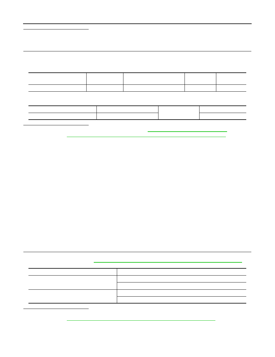
Check continuity between BCM connector and power window main switch connector.

4.

Check continuity between BCM connector and ground.

Is the inspection result normal?

YES

>> Replace power window main switch. Refer to 

PWC-126, "Removal and Installation"

. After that,

Refer to 

PWC-16, "POWER WINDOW MAIN SWITCH : Special Repair Requirement"

.

NO

>> Repair or replace harness.

FRONT POWER WINDOW SWITCH

FRONT POWER WINDOW SWITCH : Description

INFOID:0000000000961601

Power window main switch, front power window switch (passenger side), rear power window switch and BCM
transmit and receive the signal by power window serial link.
The signal mentioned below is transmitted from BCM to power window main switch, front power window
switch (passenger side) and rear power window switch.
•  Keyless power window down signal
The signal mentioned below is transmitted from power window main switch to front power window switch (pas-
senger side) and rear power window switch.
• Front passenger side door window and rear door window operation signal
• Power window control by key cylinder switch signal
• Power window lock switch signal
• Retained power operation signal 

FRONT POWER WINDOW SWITCH : Component Function Check

INFOID:0000000000961602

Power Window Serial Link Check (Passenger Side)

1.

CHECK POWER WINDOW SWITCH OUTPUT SIGNAL

Check (“CDL LOCK SW ”, “CDL UNLOCK SW”) in “DATA MONITOR” mode for “POWER DOOR LOCK SYS-
TEM” with CONSULT-III. Refer to 

DLK-50, "DOOR LOCK : CONSULT-III Function (BCM - DOOR LOCK)"

.

Is the inspection result normal?

YES

>> Power window serial link is OK.

NO

>> Refer to 

PWC-44, "FRONT POWER WINDOW SWITCH : Diagnosis Procedure"

.

FRONT POWER WINDOW SWITCH : Diagnosis Procedure

INFOID:0000000000961603

Power Window Serial Link Check (Passenger Side)

BCM connector

Terminal

Power window main switch

connector

Terminal

Continuity

M123

132

D8

14

Existed

BCM connector

Terminal

Ground

Continuity 

M123

132

Not existed

Monitor item

Condition

CDL LOCK SW 

LOCK

: ON

UNLOCK

: OFF

CDL UNLOCK SW 

LOCK

: OFF

UNLOCK

: ON

POWER WINDOW SERIAL LINK

PWC-45

< COMPONENT DIAGNOSIS >

[FRONT & REAR WINDOW ANTI-PINCH]

C

D

E

F

G

H

I

J

L

M

A

B

PWC

N

O

P

1.

CHECK POWER WINDOW SWITCH OUTPUT SIGNAL

1.

Remove key from ignition switch, and the door of driver side and passenger side is closed.

2.

Check signal between BCM connector and ground with oscilloscope when door lock and unlock switch
(driver side and passenger side) is turned to “LOCK” or “UNLOCK”.

3.

Check that signals which are shown in the figure below can be detected during 10 second just after door
lock and unlock switch (driver side and passenger side) is turned to “LOCK” or “UNLOCK”.

Is the inspection result normal?

YES

>> Power window serial link is OK.

NO

>> GO TO 2.

2.

CHECK BCM OUTPUT SIGNAL CIRCUIT 

1.

Turn ignition switch OFF.

2.

Disconnect BCM connector and front power window switch (passenger side) connector.

3.

Check continuity between BCM connector and front power window switch (passenger side) connector.

4.

Check continuity between BCM connector and ground.

Is the inspection result normal?

YES

>> Replace power window main switch. Refer to 

PWC-126, "Removal and Installation"

. After that,

Refer to 

PWC-18, "FRONT POWER WINDOW SWITCH : Special Repair Requirement"

.

NO

>> Repair or replace harness.

REAR LH

REAR LH : Description

INFOID:0000000000961604

Power window main switch, front power window switch (passenger side), rear power window switch and BCM
transmit and receive the signal by power window serial link.
The signal mentioned below is transmitted from BCM to power window main switch, front power window
switch (passenger side) and rear power window switch.
•  Keyless power window down signal
The signal mentioned below is transmitted from power window main switch to front power window switch (pas-
senger side) and rear power window switch.
• Front passenger side door window and rear door window operation signal
• Power window control by key cylinder switch signal
• Power window lock switch signal
• Retained power operation signal 

REAR LH : Component Function Check

INFOID:0000000000961605

Terminal

Signal

(Reference value)

(+)

(–)

BCM connector

Terminal 

M123

132

Ground

PIIA1297E

BCM connector

Terminal

Front power window switch (pas-

senger side) connector

Terminal

Continuity

M123

132

D38

16

Existed

BCM connector

Terminal

Ground

Continuity 

M123

132

Not existed

PWC-46

< COMPONENT DIAGNOSIS >

[FRONT & REAR WINDOW ANTI-PINCH]

POWER WINDOW SERIAL LINK

1.

CHECK POWER WINDOW SWITCH OUTPUT SIGNAL

Check (“CDL LOCK SW ”, “CDL UNLOCK SW”) in “DATA MONITOR” mode for “POWER DOOR LOCK SYS-
TEM” with CONSULT-III. Refer to 

DLK-50, "DOOR LOCK : CONSULT-III Function (BCM - DOOR LOCK)"

.

Is the inspection result normal?

YES

>> Power window serial link is OK.

NO

>> Refer to 

PWC-46, "REAR LH : Diagnosis Procedure"

.

REAR LH : Diagnosis Procedure

INFOID:0000000000961606

Power Window Serial Link Check 

1.

CHECK POWER WINDOW SWITCH OUTPUT SIGNAL

1.

Remove key from ignition switch, and the door of driver side and passenger side is closed.

2.

Check signal between BCM connector and ground with oscilloscope when door lock and unlock switch
(driver side and passenger side) is turned to “LOCK” or “UNLOCK”.

3.

Check that signals which are shown in the figure below can be detected during 10 second just after door
lock and unlock switch (driver side and passenger side) is turned to “LOCK” or “UNLOCK”.

Is the inspection result normal?

YES

>> Power window serial link is OK.

NO

>> GO TO 2.

2.

CHECK POWER WINDOW SERIAL LINK CIRCUIT

1.

Disconnect BCM connector and rear power window switch LH connector.

2.

Check continuity between BCM connector and rear power window switch LH connector.

3.

Check continuity between BCM connector and ground.

Is the inspection result normal?

YES

>> Replace power window main switch. Refer to 

PWC-126, "Removal and Installation"

. After that,

Refer to 

PWC-16, "POWER WINDOW MAIN SWITCH : Special Repair Requirement"

.

NO

>> Repair or replace harness.

Monitor item

Condition

CDL LOCK SW 

LOCK

: ON

UNLOCK

: OFF

CDL UNLOCK SW 

LOCK

: OFF

UNLOCK

: ON

Terminal

Signal

(Reference value)

(+)

(–)

BCM connector

Terminal 

M123

132

Ground

PIIA1297E

BCM connector

Terminal

Rear power window switch LH connector

Terminal

Continuity

M123

132

D54

16

Existed

BCM connector

Terminal

Ground

Continuity 

M123

132

Not existed

POWER WINDOW SERIAL LINK

PWC-47

< COMPONENT DIAGNOSIS >

[FRONT & REAR WINDOW ANTI-PINCH]

C

D

E

F

G

H

I

J

L

M

A

B

PWC

N

O

P

REAR RH

REAR RH : Description

INFOID:0000000000961607

Power window main switch, front power window switch (passenger side), rear power window switch and BCM
transmit and receive the signal by power window serial link.
The signal mentioned below is transmitted from BCM to power window main switch, front power window
switch (passenger side) and rear power window switch.
•  Keyless power window down signal
The signal mentioned below is transmitted from power window main switch to front power window switch (pas-
senger side) and rear power window switch.
• Front passenger side door window and rear door window operation signal
• Power window control by key cylinder switch signal
• Power window lock switch signal
• Retained power operation signal 

REAR RH : Component Function Check

INFOID:0000000000961608

1.

CHECK POWER WINDOW SWITCH OUTPUT SIGNAL

Check (“CDL LOCK SW ”, “CDL UNLOCK SW”) in “DATA MONITOR” mode for “POWER DOOR LOCK SYS-
TEM” with CONSULT-III. Refer to 

DLK-50, "DOOR LOCK : CONSULT-III Function (BCM - DOOR LOCK)"

.

Is the inspection result normal?

YES

>> Power window serial link is OK.

NO

>> Refer to 

PWC-47, "REAR RH : Diagnosis Procedure"

.

REAR RH : Diagnosis Procedure

INFOID:0000000000961609

Power Window Serial Link Check 

1.

CHECK POWER WINDOW SWITCH OUTPUT SIGNAL

1.

Remove key from ignition switch, and the door of driver side and passenger side is closed.

2.

Check signal between BCM connector and ground with oscilloscope when door lock and unlock switch
(driver side and passenger side) is turned to “LOCK” or “UNLOCK”.

3.

Check that signals which are shown in the figure below can be detected during 10 second just after door
lock and unlock switch (driver side and passenger side) is turned to “LOCK” or “UNLOCK”.

Is the inspection result normal?

YES

>> Power window serial link is OK.

NO

>> GO TO 2.

Monitor item

Condition

CDL LOCK SW 

LOCK

: ON

UNLOCK

: OFF

CDL UNLOCK SW 

LOCK

: OFF

UNLOCK

: ON

Terminal

Signal

(Reference value)

(+)

(–)

BCM connector

Terminal 

M123

132

Ground

PIIA1297E


Content   ..  1051  1052  1053  1054   ..