Content .. 1013 1014 1015 1016 ..
Infiniti G35 (V35) Sedan. Manual - part 1015
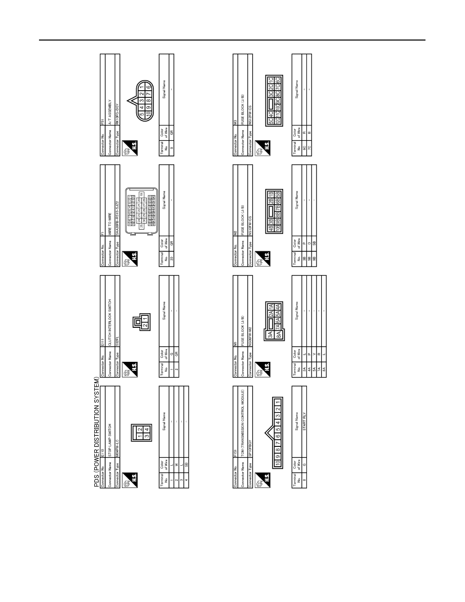
PCS-114
< ECU DIAGNOSIS >
[POWER DISTRIBUTION SYSTEM]
IPDM E/R (INTELLIGENT POWER DISTRIBUTION MODULE ENGINE ROOM)
JCMWA0024GB
|
|
|
Content .. 1013 1014 1015 1016 ..
PCS-114 < ECU DIAGNOSIS > [POWER DISTRIBUTION SYSTEM] IPDM E/R (INTELLIGENT POWER DISTRIBUTION MODULE ENGINE ROOM) JCMWA0024GB |