Infiniti G35 (V35) Sedan. Manual - part 92
AV-140
< FUNCTION DIAGNOSIS >
[BOSE AUDIO WITHOUT NAVIGATION]
DIAGNOSIS SYSTEM (AV CONTROL UNIT)
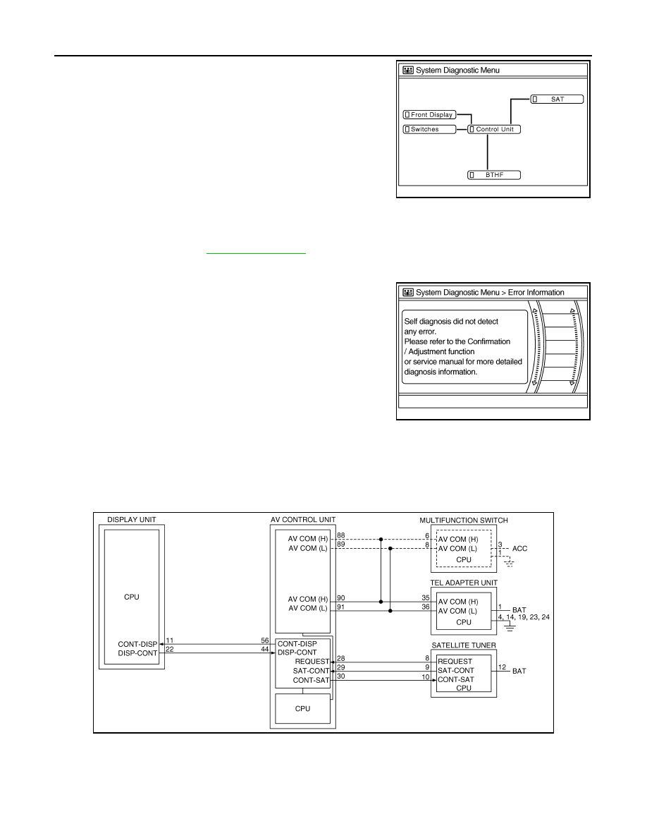
2.
Diagnosis results are displayed after the self-diagnosis is com-
pleted. The unit names and the connection lines are color-coded
according to the diagnostic results.
NOTE:
• Only the control unit (AV control unit) is displayed in red.
• Replace AV control unit if “Self-Diagnosis did not run because of a control unit malfunction” is indicated. The symptom is AV con-
trol unit internal error. Refer to
-
If multiple errors occur at the same time for a single unit, the screen switch colors are determined accord-
ing to the following order of priority: red > yellow > gray.
-
The comments of the self-diagnosis results can be viewed with a
component in the diagnosis result screen.
Detection range of self-diagnosis mode
• The self-diagnosis mode allows the technician to diagnose the connection in the communication line
between AV control unit and each unit and the internal operation of the AV control unit.
• Because the start condition of diagnosis function is a switch operation, the on board diagnosis function can-
not be started up if any malfunction is detected in the communication circuit between AV control unit and
multifunction switch.
Self-diagnosis results
Check the applicable display at the following table, and then repair the malfunctioning parts.
Self-diagnosis result chart
Diagnosis results
Unit
Con-
nection
line
Normal
Green
Green
Connection malfunction
Gray
Yellow
Unit malfunction
Note
Red
Green
JSNIA0140GB
JSNIA0141GB
JSNIA0142GB