Infiniti G35 (V35) Sedan. Manual - part 91


  Index      Infiniti     Infiniti G35 (V35) Sedan - service repair manual 2007 year


Search            


Content   ..  89  90  91  92   ..


Infiniti G35 (V35) Sedan. Manual - part 91


AV-136

< FUNCTION DIAGNOSIS >

[BOSE AUDIO WITHOUT NAVIGATION]

HANDS-FREE PHONE SYSTEM

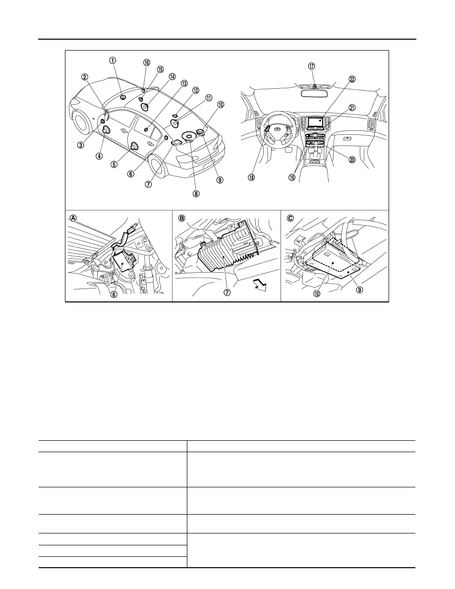
Component Description

INFOID:0000000000964635

1.

Center speaker

2.

Tweeter LH

3.

Front door squawker LH

4.

Front door woofer LH

5.

Rear door speaker LH

6.

Antenna amp.

7.

BOSE amp.

8.

Woofer

9.

TEL adapter unit

10. Satellite radio tuner

11. Rear door speaker RH

12. Satellite radio antenna

13. Auxiliary input jacks

14. Front door woofer RH

15. Front door squawker RH

16. Tweeter RH

17. Microphone

18. Steering switch

19. Preset switch

20. AV control unit

21. Multifunction switch

22. Display unit

A.

Within rear pillar finisher LH

B.

Rear parcel shelf lower part (left side) C.

Lower part of rear parcel shelf (on the 
right side)

JSNIA0171ZZ

Part name

Description

AV CONTORL UNIT

• Inputs TEL voice signal or voice guidance signal from TEL adapter unit and 

outputs it to BOSE amp. during reception.

• Connects with TEL adapter unit and AV communication and controls hands 

free phone system.

DISPLAY UNIT

• Display image is controlled by the serial communication from AV control unit.
• Inputs RGB image signal (RGB, RGB area and RGB synchronizing) from AV 

control unit and displays the status of hands free phone system.

BOSE AMP.

Inputs TEL voice signal or voice guidance signal from AV control unit and outputs 
it to front speaker and center speaker.

FRONT DOOR WOOFER

Outputs the TEL voice signal or voice guidance signal from Bose amp.

FRONT DOOR SQUAWKER

TWEETER

AV

HANDS-FREE PHONE SYSTEM

AV-137

< FUNCTION DIAGNOSIS >

[BOSE AUDIO WITHOUT NAVIGATION]

C

D

E

F

G

H

I

J

K

L

M

B

N

A

O

P

PRESET SWITCH

• Adjust the sound when using TEL.
• The operation signal is transmitted to the AV control unit via AV communica-

tion.

STEERING SWITCH

• The hands free phone system can be operated.
• Steering switch signal (operation signal) is output to AV control unit.

MICROPHONE

• Uses when operating the hands-free phone.
• Outputs Mic. signal (TEL voice signal) to the TEL adapter unit.
• The power (Mic. power supply) is supplied from the TEL adapter unit.

TEL ADAPTER UNIT

• Receives the steering switch signal (operation signal) from the steering switch.
• Inputs the TEL voice signal from TEL antenna during reception and outputs it 

to the AV control unit.

• Inputs the TEL voice signal from microphone during speech recognition and 

outputs it to the TEL antenna.

• Controlled by AV communication sent from AV control unit.

TEL ANTENNA

Connects with the portable telephone via Bluetooth

®

 and communicates the TEL 

voice signal.

Part name

Description

AV-138

< FUNCTION DIAGNOSIS >

[BOSE AUDIO WITHOUT NAVIGATION]

DIAGNOSIS SYSTEM (AV CONTROL UNIT)

DIAGNOSIS SYSTEM (AV CONTROL UNIT)

Diagnosis Description

INFOID:0000000000964636

Multifunction switch and preset switch self-diagnosis function

The ON/OFF operation (continuity) of each switch in the multifunction switch and preset switch can be
checked.

Self-diagnosis mode

• Press the “BACK” switch and the “UP” switch of the 4-direction

switches within 10 seconds after turning the ignition switch from
OFF to ACC and hold them for 3 seconds or more.  The buzzer
sounds, all indicators of the preset switch illuminate, and the self-
diagnosis mode starts.

• The continuity of each switch at the ON position can be checked

by pressing the switch. The buzzer sounds if the switch is normal.

CAUTION:

The hazard switch and CD eject switch cannot be checked.

Finishing self-diagnosis mode

Self-diagnosis mode is canceled when turning the ignition switch OFF.

MULTI AV SYSTEM on board diagnosis function

• The AV control unit diagnosis function starts up with multifunction switch operation and the AV control unit

performs a diagnosis for each unit in the system during the on board diagnosis.

• Perform a CONSULT-III diagnosis if the on board diagnosis does not start, e.g., the screen does not display

anything, the multifunction switch does not function. etc.

On board diagnosis

Description

• The trouble diagnosis function has a self-diagnosis mode for conducting trouble diagnosis automatically and

a confirmation/adjustment mode for operating manually.

• Self-diagnosis mode performs the AV control unit diagnosis and the connection diagnosis between each of

the units that make up the system, and it indicates the results to the display.

• The confirmation/adjustment mode allows the technician to check, modify or adjust the vehicle signals and

set values, as well as to monitor the system error records and system communication status. The check,
modify or adjust actions generally require human intervention and judgment (the system cannot make judg-
ment automatically. 

On board diagnosis item

JSNIA0136GB

Mode

Description

Self Diagnosis

• AV control unit diagnosis 
• Perform the connection diagnosis between each of the units.

AV

DIAGNOSIS SYSTEM (AV CONTROL UNIT)

AV-139

< FUNCTION DIAGNOSIS >

[BOSE AUDIO WITHOUT NAVIGATION]

C

D

E

F

G

H

I

J

K

L

M

B

N

A

O

P

STARTING PROCEDURE

1.

Start the engine.

2.

Turn the audio system OFF.

3.

While pushing the “SETTING” button, turn the volume control
dial clockwise or counterclockwise for 40 clicks or more. (When
the self-diagnosis mode is started, a short beep will be heard.)
• Shifting from current screen to previous screen is performed

by pushing “BACK” button.

4.

The trouble diagnosis initial screen is displayed, and then the
items of “Self Diagnosis” and “Confirmation/Adjustment” can be
selected.

Self-diagnosis mode

1.

Start the self-diagnosis function and select “Self-diagnosis”.

-

Self-diagnosis subdivision screen is displayed, and the self-
diagnosis mode starts.

-

The bar graph visible on the center of the self-diagnosis subdivi-
sion screen indicates progress of the trouble diagnosis.

Confirmation/
Adjustment

Display Diagnosis

The confirmations of the tint with the color spectrum bar display and 
shading of color with the gradation bar display can be performed.

Vehicle Signals

Diagnosis of signals can be performed for vehicle speed, parking brake, 
lights, ignition switch, and reverse.

Speaker Test

The connection of a speaker can be confirmed by test tone.

Climate Control

Start auto air conditioner system self-diagnosis.

Error History

The system malfunction and the frequency when occurred in the past are 
displayed. When the malfunctioning item is selected, the time and place 
that the selected malfunction last occurred are displayed.

Vehicle CAN Diagnosis

The transmitting/receiving of CAN communication can be monitored.

AV COMM Diagnosis

The communication condition of each unit of Multi AV system can be 
monitored.

Delete Unit Connection Log

Erase the connection history of unit and error history

Initialize Settings

Initializes the AV control unit memory.

Mode

Description

JSNIA0137GB

JSNIA0138GB

JSNIA0139GB


Content   ..  89  90  91  92   ..