Infiniti G35 (V35) Sedan. Manual - part 90
AV-132
< FUNCTION DIAGNOSIS >
[BOSE AUDIO WITHOUT NAVIGATION]
AUDIO SYSTEM
AUDIO SYSTEM
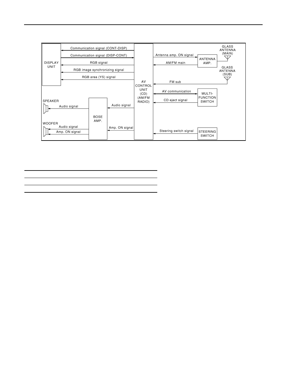
System Diagram
INFOID:0000000000964628
System Description
INFOID:0000000000964629
The audio system is equipped with following function. Each function can be operated with the multifunction switch, preset switch or steering
switch. It indicates the operation status of AUDIO to the display.
Function description
Operating signal
Operation of the audio system can be performed with the multi function switch, preset switch or steering
switch.
• Operating signal is transmitted to AV control unit with AV communication when it is operated by multi func-
tion switch or preset switch. The CD ejection operating signal is performed by hardwire.
• Operating signal is transmitted to AV control unit with steering switch signal when it is operated by steering
switch.
Screen display
• The display switching of the screen is performed with the communication signal between the display and the
AV control unit.
• The image signal to display operating condition is performed with RGB signal, RGB area signal and RGB
image synchronizing signal.
AM/FM Radio Mode
• AM/FM radio tuner is built into AV control unit.
• Audio signal is received by glass antenna, next it is amplified by antenna amp, and finally it is input to AV
control unit. Audio signal is input to BOSE amp. and BOSE amp. outputs to each speaker for AV control unit.
CD Mode
• CD function is built into AV control unit.
• AV control unit outputs audio signal to BOSE amp. and BOSE amp. outputs to each speaker when CD is
inserted to AV control unit.
Component Parts Location
INFOID:0000000000964630
JSNIA0218GB
Function
AM/FM radio
CD