Infiniti G20 (P11). Manual - part 491
SMT637A
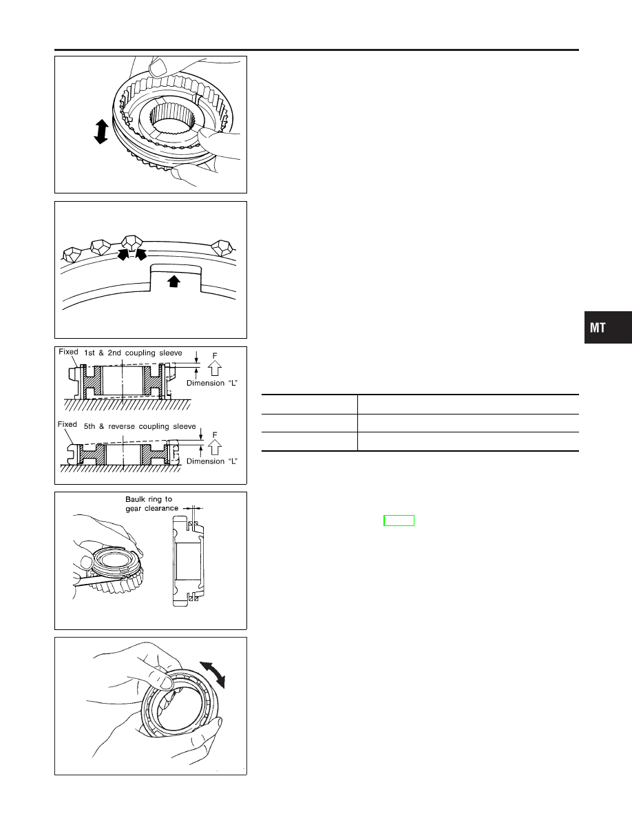
Synchronizers
NCMT0014S02
I
Check spline area of coupling sleeves, hubs and gears for
wear or cracks.
I
Check baulk rings for cracks or deformation.
I
Check insert springs for wear or deformation.
SMT867D
I
If any crack, damage, or excessive wear is found on cam face
of baulk ring or working face of insert, replace it.
SMT868D
I
Measure the movement (play, dimension “L”) of 1st & 2nd
coupling sleeve and 5th & reverse coupling sleeve with their
end fixed and the other end lifted as shown in the figure. If the
movement exceeds specification, replace the sleeve.
Coupling sleeve
Length “L”
1st & 2nd
0 - 0.68 mm (0 - 0.0268 in)
5th & Reverse
0 - 0.89 mm (0 - 0.0350 in)
SMT140
I
Measure clearance between baulk ring and gear.
Clearance between baulk ring and gear:
Refer to SDS, MT-57.
SMT148A
Bearing
NCMT0014S03
I
Make sure bearings roll freely and are free from noise, cracks,
pitting or wear.
GI
MA
EM
LC
EC
FE
CL
AT
AX
SU
BR
ST
RS
BT
HA
SC
EL
IDX
REPAIR FOR COMPONENT PARTS
Mainshaft and Gears (Cont’d)
MT-33