Infiniti G20 (P11). Manual - part 473
DISASSEMBLY AND ASSEMBLY
NCLC0006
SLC265BA
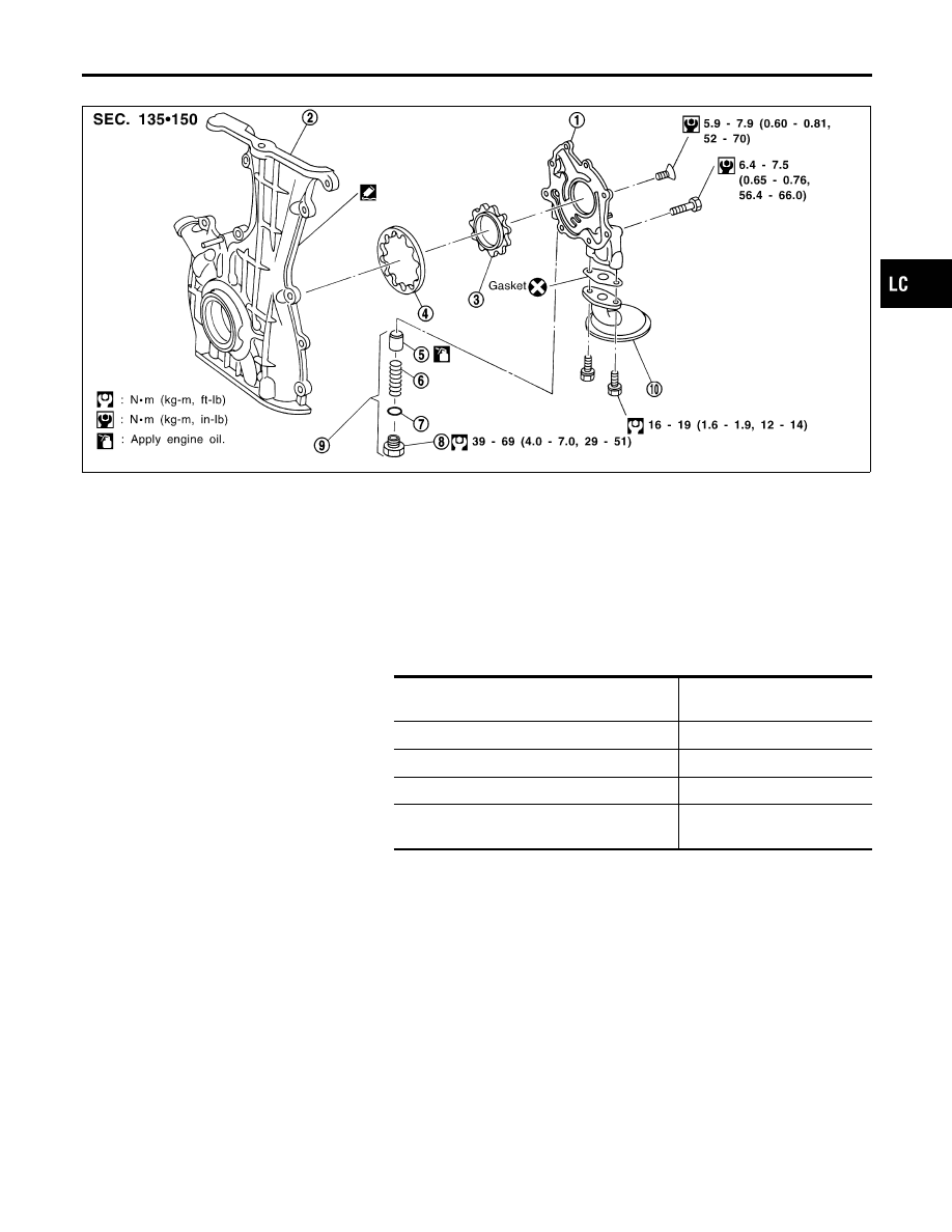
1.
Oil pump cover
2.
Front cover
3.
Inner gear
4.
Outer gear
5.
Regulator valve
6.
Spring
7.
Shim
8.
Plug
9.
Regulator valve assembly
10. Oil strainer
INSPECTION
NCLC0007
Using a feeler gauge, check the following clearances:
Standard clearance:
Unit: mm (in)
Body to outer gear radial clearance 1
0.114 - 0.200
(0.0045 - 0.0079)
Inner gear to outer gear tip clearance 2
Below 0.18 (0.0071)
Body to inner gear clearance 3
0.05 - 0.09 (0.0020 - 0.0035)
Body to outer gear axial clearance 4
0.05 - 0.11 (0.0020 - 0.0043)
Inner gear to brazed portion of housing clear-
ance 5
0.045 - 0.091
(0.0018 - 0.0036)
I
If the tip clearance (2) exceeds the limit, replace gear set.
I
If body to gear clearances (1, 3, 4, 5) exceed the limit,
replace front cover assembly.
GI
MA
EM
EC
FE
CL
MT
AT
AX
SU
BR
ST
RS
BT
HA
SC
EL
IDX
ENGINE LUBRICATION SYSTEM
Oil Pump (Cont’d)
LC-5