Infiniti G20 (P11). Manual - part 468
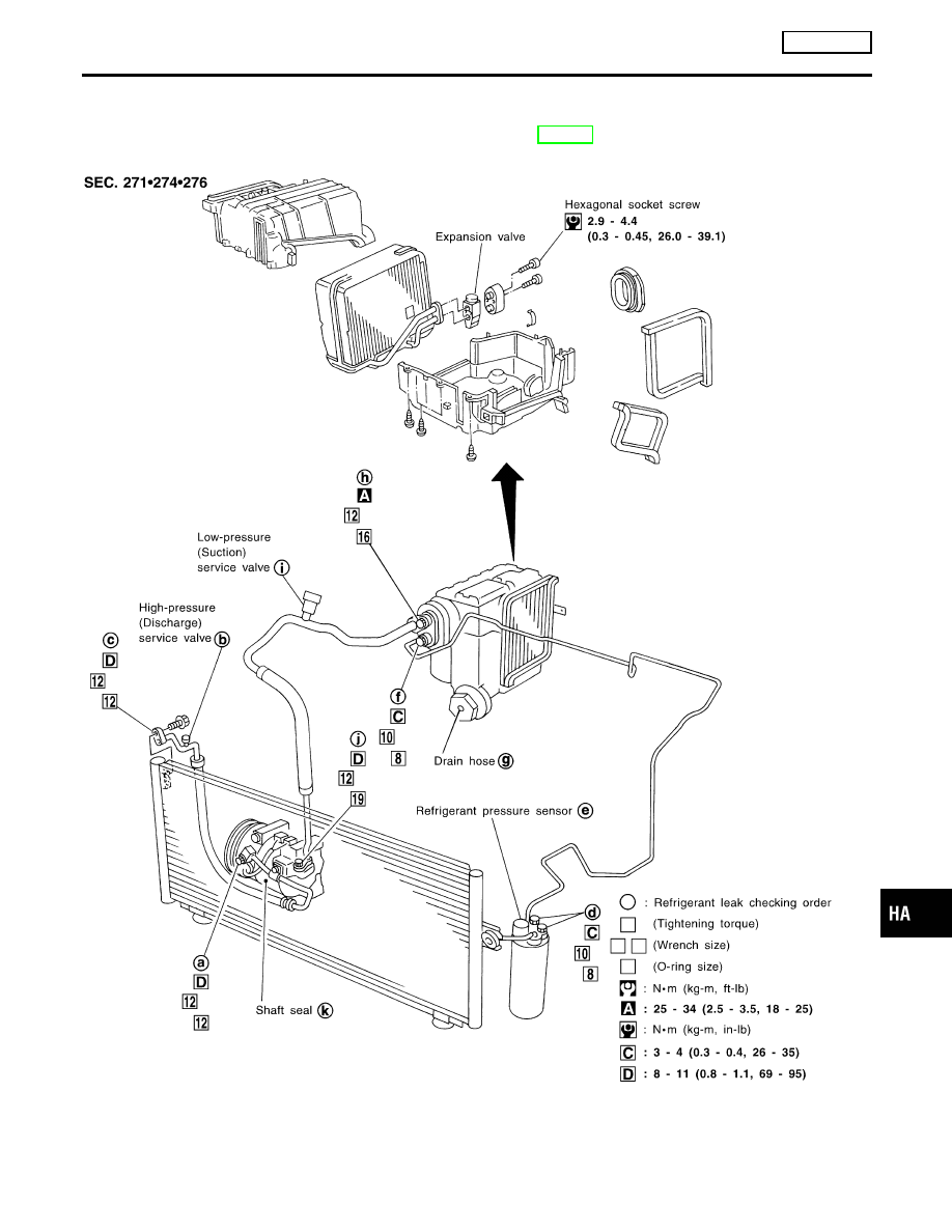
Refrigerant Lines
REMOVAL AND INSTALLATION
=NCHA0167
I
Refer to page HA-126 reading “Precautions for Refrigerant
Connection”.
RHA533H
GI
MA
EM
LC
EC
FE
CL
MT
AT
AX
SU
BR
ST
RS
BT
SC
EL
IDX
SERVICE PROCEDURE
MANUAL
Refrigerant Lines
HA-203