Infiniti G20 (P11). Manual - part 455


  Index      Infiniti     Infiniti G20 (P11) - service repair manual 1999-2002 year


Search            


Content   ..  453  454  455  456   ..


Infiniti G20 (P11). Manual - part 455


MAIN POWER SUPPLY AND GROUND CIRCUIT CHECK

=NCHA0132

Power Supply Circuit Check

NCHA0132S01

Check power supply circuit for air conditioner system.
Refer to EL-10, “Wiring Diagram — POWER —”.

A/C SYSTEM CIRCUIT

NCHA0191

SYMPTOM:

I

A/C system does not come on.

RHA093H

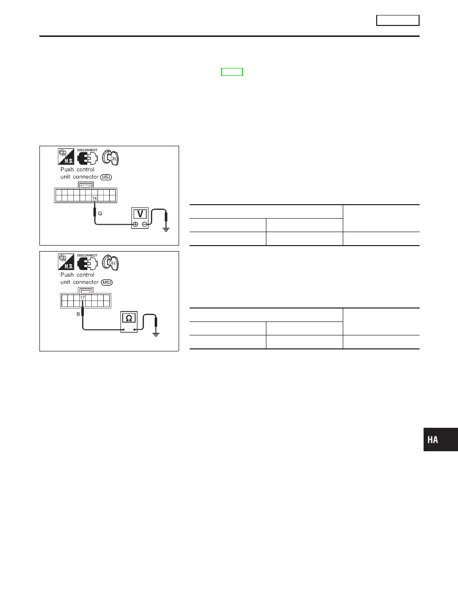
Push Control Unit Check

NCHA0191S01

Check power supply circuit for push control unit with ignition switch
ON.
1)

Disconnect push control unit harness connector.

2)

Connect voltmeter from harness side.

3)

Measure voltage across terminal No. 14 and body ground.

Voltmeter terminal

Voltage

(+)

(−)

14

Body ground

Approx. 12V

RHA094H

Check body ground circuit for push control unit with ignition switch
OFF.
1)

Disconnect push control unit harness connector.

2)

Connect ohmmeter from harness side.

3)

Check for continuity between terminal No. 17 and body
ground.

Ohmmeter terminal

Continuity

(+)

(−)

17

Body ground

Yes

GI

MA

EM

LC

EC

FE

CL

MT

AT

AX

SU

BR

ST

RS

BT

SC

EL

IDX

TROUBLE DIAGNOSES

MANUAL

A/C System (Cont’d)

HA-151

Intake Door

TROUBLE DIAGNOSIS PROCEDURE FOR INTAKE DOOR

=NCHA0133

SYMPTOM:

I

Intake door does not change.

INSPECTION FLOW

SHA182F

*1: HA-153

*2: HA-148

*3: HA-147

RHA096H

COMPONENT DESCRIPTION

NCHA0134

Intake Door Motor

NCHA0134S01

The intake door motor is attached to the intake unit. It rotates so
that air is drawn from inlets set by each mode switches. Motor
rotation is conveyed to a lever which activates the intake door.
RECIRCULATION switch is canceled by MODE switch in DEF and
D/F modes.

TROUBLE DIAGNOSES

MANUAL

Intake Door

HA-152

INTAKE DOOR MOTOR CIRCUIT

=NCHA0135

SYMPTOM:

I

Intake door does not change.

1

CHECK POWER SUPPLY FOR INTAKE DOOR MOTOR

Disconnect intake door motor harness connector.
Do approx. 12 volts exist between push control unit harness terminal Nos. 9, 11 and body ground?

SHA366F

Yes or No

Yes

©

GO TO 3.

No

©

GO TO 2.

2

CHECK CIRCUIT CONTINUITY BETWEEN INTAKE DOOR MOTOR AND PUSH CONTROL UNIT

Check circuit continuity between push control unit harness terminal Nos. 9 (11) and intake door motor harness terminal
Nos. 7 (6).

Continuity should exist.

RHA098HA

If OK, check harness for short.

Yes or No

Yes

©

Replace push control unit.

No

©

Repair harness or connector.

GI

MA

EM

LC

EC

FE

CL

MT

AT

AX

SU

BR

ST

RS

BT

SC

EL

IDX

TROUBLE DIAGNOSES

MANUAL

Intake Door (Cont’d)

HA-153

3

CHECK CIRCUIT CONTINUITY OF INTAKE DOOR MOTOR

Check circuit continuity between intake door motor harness terminal No. 6 and No. 7.

RHA099HA

OK or NG

OK

©

GO TO 4.

NG

©

Replace intake door motor.

4

CHECK INTAKE DOOR LINKAGE

Refer to Control Linkage Adjustment. (HA-155)

OK or NG

OK

©

GO TO 5.

NG

©

Repair or adjust.

5

CHECK FOR OUTPUT OF PUSH CONTROL UNIT

Do approx. 5 volts exist between intake door motor harness terminal Nos. 1, 4 and body ground?

RHA100H

Yes or No

Yes

©

GO TO 6.

No

©

GO TO 7.

TROUBLE DIAGNOSES

MANUAL

Intake Door (Cont’d)

HA-154


Content   ..  453  454  455  456   ..