Infiniti G20 (P11). Manual - part 448
Auto
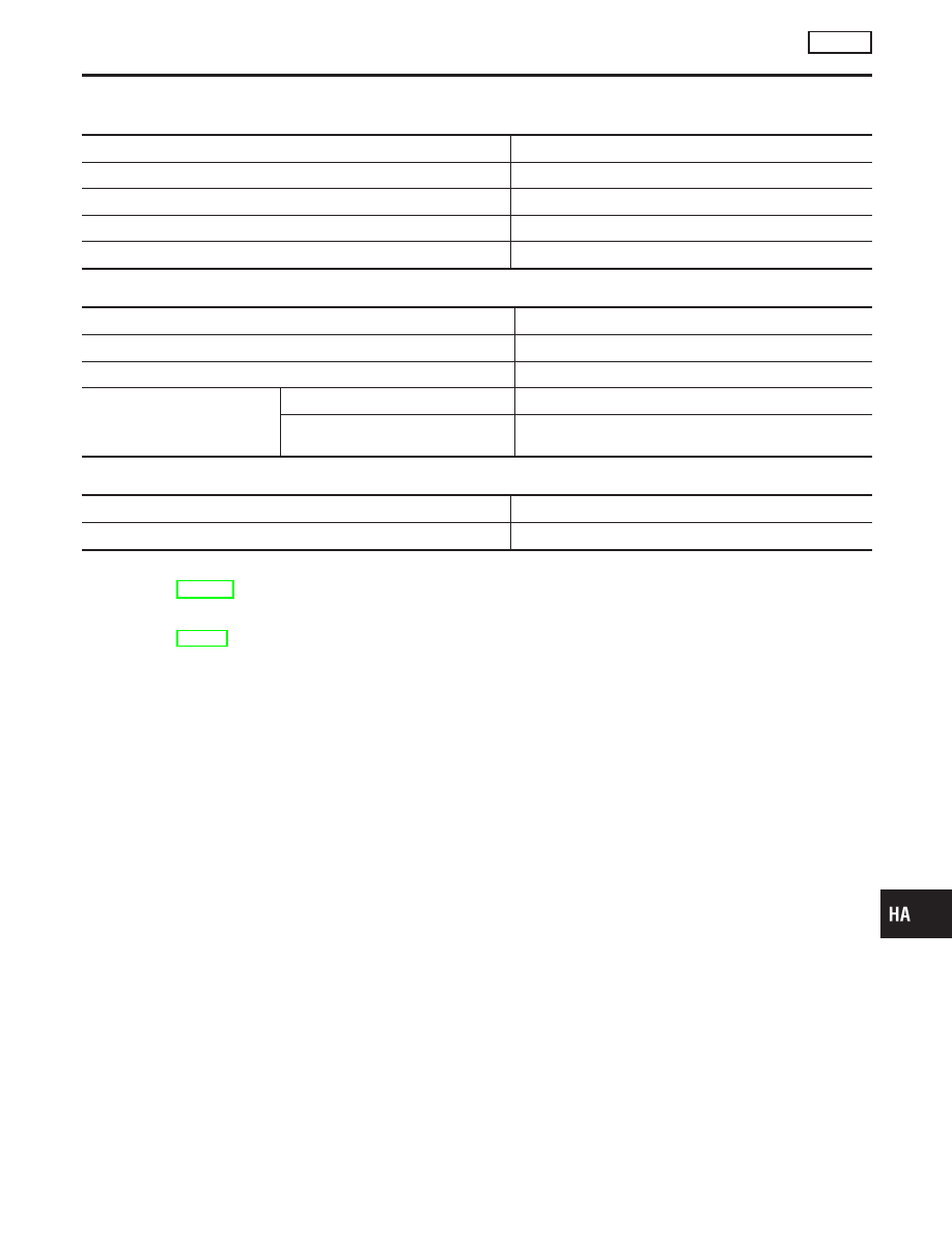
COMPRESSOR
NCHA0081
Model
ZEXEL make DKV-14G
Type
Vane rotary
Displacement
cm
3
(cu in)/rev.
140 (8.54)
Direction of rotation
Clockwise (viewed from drive end)
Drive belt
Poly V
LUBRICANT
NCHA0082
Model
ZEXEL make DKV-14G
Name
Nissan A/C System Oil Type R
Part number
KLH00-PAGR0
Capacity
m
(US fl oz, Imp fl oz)
Total in system
180 (6.1, 6.3)
Compressor (Service part) charging
amount
180 (6.1, 6.3)
REFRIGERANT
NCHA0083
Type
HFC-134a (R-134a)
Capacity
kg (lb)
0.55 - 0.65 (1.21 - 1.43)
ENGINE IDLING SPEED (WHEN A/C IS ON)
NCHA0084
I
Refer to EC-632, “Idle Speed and Ignition Timing”.
BELT TENSION
NCHA0085
I
Refer to MA-13, “Checking Drive Belts”.
GI
MA
EM
LC
EC
FE
CL
MT
AT
AX
SU
BR
ST
RS
BT
SC
EL
IDX
SERVICE DATA AND SPECIFICATIONS (SDS)
AUTO
Auto
HA-123