Infiniti G20 (P11). Manual - part 447


  Index      Infiniti     Infiniti G20 (P11) - service repair manual 1999-2002 year


Search            


Content   ..  445  446  447  448   ..


Infiniti G20 (P11). Manual - part 447


5.

With the A/C operating (compressor running), inject one bottle
(1/4 ounce/7.4 cc) of fluorescent dye through the low-pressure
service valve using dye injector tool J-41459 (refer to the
manufacture’s operating instructions).

6.

With the engine still running, disconnect the injector tool from
the service fitting.

CAUTION:

Be careful not to allow dye to spray or drip when disconnect-
ing the injector from the system.
NOTE:
If repairing the A/C system or replacing a component, pour the dye
directly into the open system connection and proceed with the ser-
vice procedures.
7.

Operate the A/C system for a minimum of 20 minutes to mix
the dye with the system oil. Depending on the leak size, oper-
ating conditions and location of the leak, it may take from min-
utes to days for the dye to penetrate a leak and become visible.

SHA196FA

ELECTRONIC REFRIGERANT LEAK DETECTOR

NCHA0205

Precautions for Handling Leak Detector

NCHA0205S01

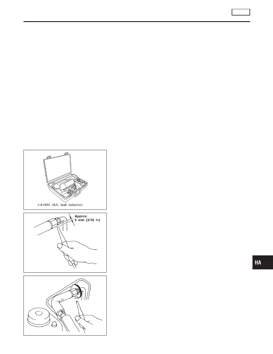
When performing a refrigerant leak check, use a J-41995 A/C leak
detector or equivalent. Ensure that the instrument is calibrated and
set properly per the operating instructions.
The leak detector is a delicate device. In order to use the leak
detector properly, read the operating instructions and perform any
specified maintenance.

SHA707EA

1.

Position probe approximately 5 mm (3/16 in) away from point
to be checked.

SHA706E

2.

When testing, circle each fitting completely with probe.

GI

MA

EM

LC

EC

FE

CL

MT

AT

AX

SU

BR

ST

RS

BT

SC

EL

IDX

SERVICE PROCEDURE

AUTO

Refrigerant Lines (Cont’d)

HA-119

SHA708EA

3.

Move probe along component approximately 25 to 50 mm (1
to 2 in)/sec.

Checking Procedure

NCHA0205S02

To prevent inaccurate or false readings, make sure there is no
refrigerant vapor, shop chemicals, or cigarette smoke in the
vicinity of the vehicle. Perform the leak test in calm area (low
air/wind movement) so that the leaking refrigerant is not dis-
persed.
1.

Turn engine off.

2.

Connect a suitable A/C manifold gauge set to the A/C service
ports.

3.

Check if the A/C refrigerant pressure is at least 345 kPa (3.52
kg/cm

2

, 50 psi) above 16°C (61°F). If less than specification,

recover/evacuate and recharge the system with the specified
amount of refrigerant.

NOTE:
At temperatures below 16°C (61°F), leaks may not be detected
since the system may not reach 345 kPa (3.52 kg/cm

2

, 50 psi).

4.

Conduct the leak test from the high side (compressor dis-
charge to evaporator inlet f) to the low side (evaporator drain
hose to shaft seal k). Refer to HA-117. Perform a leak check
for the following areas carefully. Clean the component to be
checked and move the leak detector probe completely around
the connection/component.

I

Compressor
Check the fitting of high and low pressure hoses, relief valve
and shaft seal.

I

Liquid tank
Check the pressure switch, tube fitting, weld seams and the
fusible plug mount.

I

Service valves
Check all around the service valves. Ensure service valve caps
are secured on the service valves (to prevent leaks).

NOTE:
After removing A/C manifold gauge set from service valves, wipe
any residue from valves to prevent any false readings by leak
detector.

I

Cooling unit (Evaporator)
With engine OFF, turn blower fan on “High” for at least 15
seconds to dissipate any refrigerant trace in the cooling unit.
Wait a minimum of 10 minutes accumulation time (refer to the
manufacturer’s recommended procedure for actual wait time)
before inserting the leak detector probe into the drain hose.
Keep the probe inserted for at least ten seconds. Use caution
not to contaminate the ptobe tip with water or dirt that may be
in the drain hose.

SERVICE PROCEDURE

AUTO

Refrigerant Lines (Cont’d)

HA-120

5.

If a leak detector detects a leak, verify at least once by blow-
ing compressed air into area of suspected leak, then repeat
check as outlined above.

6.

Do not stop when one leak is found. Continue to check for
additional leaks at all system components.
If no leaks are found, perform steps 7 - 10.

7.

Start engine.

8.

Set the heater A/C control as follows:

1)

A/C switch ON.

2)

Face mode

3)

Recirculation switch ON

4)

Max cold temperature

5)

Fan speed high

9.

Run engine at 1,500 rpm for at least 2 minutes.

10. Turn engine off and perform leak check again following steps

4 through 6 above.

SHA839E

Refrigerant leaks should be checked immediately after
stopping the engine. Begin with the leak detector at the
compressor. The pressure on the high pressure side will
gradually drop after refrigerant circulation stops and pres-
sure on the low pressure side will gradually rise, as shown
in the graph. Some leaks are more easily detected when
pressure is high.

11. Before connecting ACR4 to vehicle, check ACR4 gauges. No

refrigerant pressure should be displayed. If pressure is
displayed, recover refrigerant from equipment lines and then
check refrigerant purity.

12. Confirm refrigerant purity in supply tank using ACR4 and refrig-

erant identifier.

13. Confirm refrigerant purity in vehicle A/C system using ACR4

and refrigerant identifier.

14. Discharge A/C system using approved refrigerant recovery

equipment. Repair the leaking fitting or component as neces-
sary.

15. Evacuate and recharge A/C system and perform the leak test

to confirm no refrigerant leaks.

16. Conduct A/C performance test to ensure system works

properly.

GI

MA

EM

LC

EC

FE

CL

MT

AT

AX

SU

BR

ST

RS

BT

SC

EL

IDX

SERVICE PROCEDURE

AUTO

Refrigerant Lines (Cont’d)

HA-121

Belt

TENSION ADJUSTMENT

NCHA0079

I

Refer to MA-13, “Checking Drive Belt”.

Idle Air Control Valve (IACV) — Auxiliary Air
Control (AAC) Valve

INSPECTION

NCHA0189

I

Refer to EC-436, “System Description” and HA-14.

RHA042G

Ventilation Air Filter

FUNCTION

NCHA0109

Air inside passenger compartment is kept clean at either recircula-
tion or fresh mode by installing ventilation air filter into cooling unit.

SHA868E

REPLACEMENT TIMING

NCHA0110

Replace ventilation air filter.
Refer to MA-6, “PERIODIC MAINTENANCE”.
Caution label is fixed inside the glove box.

SHA192F

REPLACEMENT PROCEDURES

NCHA0111

I

Remove glove box.

I

Remove instrument reinforcement from instrument panel.

I

Remove ventilation air filter fixed clip.

I

Take out the lower side ventilation air filter from cooling unit.

I

Then slide upper side filter to the bottom position and take off
the ventilation air filter from the cooling unit.

I

Replace with new one and reinstall on cooling unit.

I

Reinstall instrument reinforcement, glove box and undercover.

SERVICE PROCEDURE

AUTO

Belt

HA-122


Content   ..  445  446  447  448   ..