Infiniti G20 (P11). Manual - part 431
SYSTEM DESCRIPTION
=NCHA0059
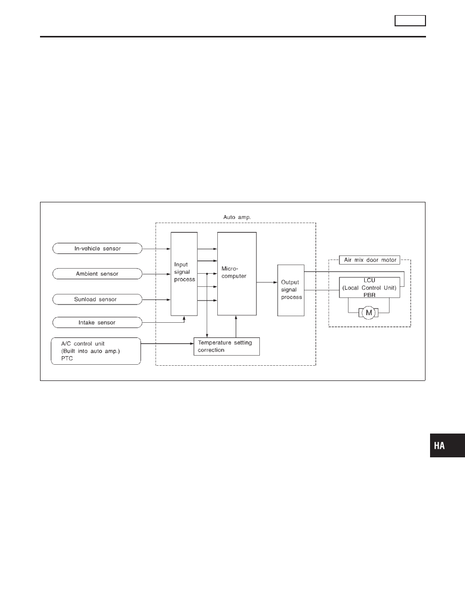
Component Parts
NCHA0059S01
Air mix door control system components are:
1) Auto amp.
2) Air mix door motor (LCU)
3) In-vehicle sensor
4) Ambient sensor
5) Sunload sensor
6) Intake sensor
System Operation
NCHA0059S02
The auto amplifier receives data from each of the sensors. The amplifier sends air mix door and mode door
opening angle data to the air mix door motor LCU and mode door motor LCU.
The air mix door motor and mode door motor read their respective signals according to the address signal.
Opening angle indication signals received from the auto amplifier and each of the motor position sensors are
compared by the LCUs in each motor with the existing decision and opening angles. Subsequently, HOT/
COLD or DEFROST/VENT operation is selected. The new selection data is returned to the auto amplifier.
RHA424GB
GI
MA
EM
LC
EC
FE
CL
MT
AT
AX
SU
BR
ST
RS
BT
SC
EL
IDX
TROUBLE DIAGNOSES
AUTO
Air Mix Door Motor (Cont’d)
HA-55