Infiniti G20 (P11). Manual - part 428
RHA654F
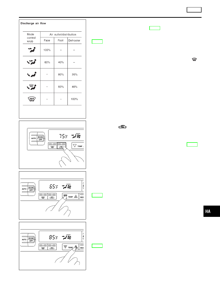
3.
Confirm that discharge air comes out according to the air dis-
tribution table at left.
Refer to “Discharge Air Flow” (HA-21).
Intake door position is checked in the next step.
If NG, go to trouble diagnosis procedure for mode door motor
(HA-48).
If OK, continue with next check.
NOTE:
Confirm that the compressor clutch is engaged (visual inspec-
tion) and intake door position is at FRESH when the DEF
is
selected.
RHA459G
4. Check Recirculation
NCHA0019S0204
1.
Press REC
switch.
Recirculation indicator should illuminate.
2.
Listen for intake door position change (you should hear blower
sound change slightly).
If NG, go to trouble diagnosis procedure for intake door (HA-58).
If OK, continue with next check.
RHA460G
5. Check Temperature Decrease
NCHA0019S0205
1.
Press the temperature decrease button until 18°C (65°F) is
displayed.
2.
Check for cold air at discharge air outlets.
If NG, go to trouble diagnosis procedure for insufficient cooling
(HA-80).
If OK, continue with next check.
RHA461G
6. Check Temperature Increase
NCHA0019S0206
1.
Press the temperature increase button until 32°C (85°F) is
displayed.
2.
Check for hot air at discharge air outlets.
If NG, go to trouble diagnosis procedure for insufficient heating
(HA-88).
If OK, continue with next check.
GI
MA
EM
LC
EC
FE
CL
MT
AT
AX
SU
BR
ST
RS
BT
SC
EL
IDX
TROUBLE DIAGNOSES
AUTO
Operational Check (Cont’d)
HA-43