Infiniti G20 (P11). Manual - part 411


  Index      Infiniti     Infiniti G20 (P11) - service repair manual 1999-2002 year


Search            


Content   ..  409  410  411  412   ..


Infiniti G20 (P11). Manual - part 411


voltage; open is further down the circuit than SW1.
no voltage; open is between fuse block and SW1 (point A).

4)

Close SW1 and probe at relay.
voltage; open is further down the circuit than the relay.
no voltage; open is between SW1 and relay (point B).

5)

Close the relay and probe at the solenoid.
voltage; open is further down the circuit than the solenoid.
no voltage; open is between relay and solenoid (point C).

Any powered circuit can be diagnosed using the approach in the
above example.

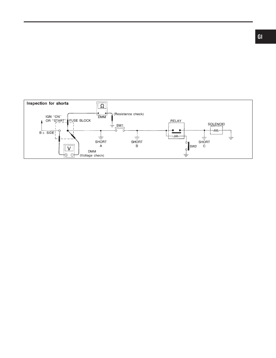
TESTING FOR “SHORTS” IN THE CIRCUIT

NCGI0005S0303

To simplify the discussion of shorts in the system please refer to
the schematic below.

SGI847

Resistance Check Method
1)

Disconnect the battery negative cable and remove the blown
fuse.

2)

Disconnect all loads (SW1 open, relay disconnected and sole-
noid disconnected) powered through the fuse.

3)

Connect one probe of the ohmmeter to the load side of the fuse
terminal. Connect the other probe to a known-good ground.

4)

With SW1 open, check for continuity.
continuity; short is between fuse terminal and SW1 (point A).
no continuity; short is further down the circuit than SW1.

5)

Close SW1 and disconnect the relay. Put probes at the load
side of fuse terminal and a known-good ground. Then, check
for continuity.
continuity; short is between SW1 and the relay (point B).
no continuity; short is further down the circuit than the relay.

6)

Close SW1 and jump the relay contacts with jumper wire. Put
probes at the load side of fuse terminal and a known-good
ground. Then, check for continuity.
continuity; short is between relay and solenoid (point C).
no continuity; check solenoid, retrace steps.

Voltage Check Method
1)

Remove the blown fuse and disconnect all loads (i.e. SW1
open, relay disconnected and solenoid disconnected) powered
through the fuse.

2)

Turn the ignition key to the ON or START position. Verify bat-
tery voltage at the B + side of the fuse terminal (one lead on
the B + terminal side of the fuse block and one lead on a
known-good ground).

3)

With SW1 open and the DMM leads across both fuse
terminals, check for voltage.
voltage; short is between fuse block and SW1 (point A).
no voltage; short is further down the circuit than SW1.

MA

EM

LC

EC

FE

CL

MT

AT

AX

SU

BR

ST

RS

BT

HA

SC

EL

IDX

HOW TO PERFORM EFFICIENT DIAGNOSIS FOR AN ELECTRICAL INCIDENT

Circuit Inspection (Cont’d)

GI-29

4)

With SW1 closed, relay and solenoid disconnected and the
DMM leads across both fuse terminals, check for voltage.
voltage; short is between SW1 and the relay (point B).
no voltage; short is further down the circuit than the relay.

5)

With SW1 closed, relay contacts jumped with fused jumper
wire check for voltage.
voltage; short is down the circuit of the relay or between the
relay and the disconnected solenoid (point C).
no voltage; retrace steps and check power to fuse block.

GROUND INSPECTION

NCGI0005S0304

Ground connections are very important to the proper operation of
electrical and electronic circuits. Ground connections are often
exposed to moisture, dirt and other corrosive elements. The corro-
sion (rust) can become an unwanted resistance. This unwanted
resistance can change the way a circuit works.
Electronically controlled circuits are very sensitive to proper
grounding. A loose or corroded ground can drastically affect an
electronically controlled circuit. A poor or corroded ground can eas-
ily affect the circuit. Even when the ground connection looks clean,
there can be a thin film of rust on the surface.
When inspecting a ground connection follow these rules:
1)

Remove the ground bolt or screw.

2)

Inspect all mating surfaces for tarnish, dirt, rust, etc.

3)

Clean as required to assure good contact.

4)

Reinstall bolt or screw securely.

5)

Inspect for “add-on” accessories which may be interfering with
the ground circuit.

6)

If several wires are crimped into one ground eyelet terminal,
check for proper crimps. Make sure all of the wires are clean,
securely fastened and providing a good ground path. If multiple
wires are cased in one eyelet make sure no ground wires have
excess wire insulation.

SGI853

VOLTAGE DROP TESTS

NCGI0005S0305

Voltage drop tests are often used to find components or circuits
which have excessive resistance. A voltage drop in a circuit is
caused by a resistance when the circuit is in operation.
Check the wire in the illustration. When measuring resistance with

HOW TO PERFORM EFFICIENT DIAGNOSIS FOR AN ELECTRICAL INCIDENT

Circuit Inspection (Cont’d)

GI-30

ohmmeter, contact by a single strand of wire will give reading of 0
ohms. This would indicate a good circuit. When the circuit operates,
this single strand of wire is not able to carry the current. The single
strand will have a high resistance to the current. This will be picked
up as a slight voltage drop.
Unwanted resistance can be caused by many situations as follows:

I

Undersized wiring (single strand example)

I

Corrosion on switch contacts

I

Loose wire connections or splices.

If repairs are needed always use wire that is of the same or larger
gauge.
Measuring Voltage Drop — Accumulated Method
1)

Connect the voltmeter across the connector or part of the cir-
cuit you want to check. The positive lead of the voltmeter
should be closer to power and the negative lead closer to
ground.

2)

Operate the circuit.

3)

The voltmeter will indicate how many volts are being used to
“push” current through that part of the circuit.

Note in the illustration that there is an excessive 4.1 volt drop
between the battery and the bulb.

SGI974

Measuring Voltage Drop — Step by Step
The step by step method is most useful for isolating excessive
drops in low voltage systems (such as those in “Computer Con-
trolled Systems”).
Circuits in the “Computer Controlled System” operate on very low
amperage.
The (Computer Controlled) system operations can be adversely
affected by any variation in resistance in the system. Such resis-
tance variation may be caused by poor connection, improper
installation, improper wire gauge or corrosion.
The step by step voltage drop test can identify a component or wire
with too much resistance.

MA

EM

LC

EC

FE

CL

MT

AT

AX

SU

BR

ST

RS

BT

HA

SC

EL

IDX

HOW TO PERFORM EFFICIENT DIAGNOSIS FOR AN ELECTRICAL INCIDENT

Circuit Inspection (Cont’d)

GI-31

SGI854

CONTROL UNIT CIRCUIT TEST

NCGI0005S0306

System Description: When the switch is ON, the control unit lights
up the lamp.

MGI034A

Input-output voltage chart

Pin No.

Item

Condition

Voltage
value V

In case of high resistance such as single strand V*

1

Switch

Switch ON

Battery voltage

Lower than battery voltage Approx. 8 (Example)

Switch OFF

Approx. 0

Approx. 0

2

Lamp

Switch ON

Battery voltage

Approx. 0 (Inoperative lamp)

Switch OFF

Approx. 0

Approx. 0

The voltage value is based on the body ground.
* : If high resistance exists in the switch side circuit (caused by a single strand), terminal 1 does not detect battery voltage. Control unit
does not detect the switch is ON even if the switch does not turn ON. Therefore, the control unit does not supply power to light up the
lamp.

HOW TO PERFORM EFFICIENT DIAGNOSIS FOR AN ELECTRICAL INCIDENT

Circuit Inspection (Cont’d)

GI-32


Content   ..  409  410  411  412   ..