Infiniti G20 (P11). Manual - part 408
SGI860
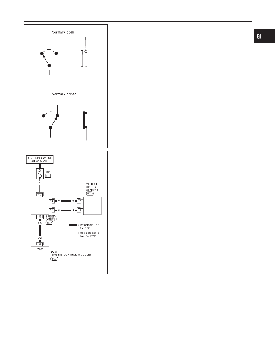
SWITCH POSITIONS
NCGI0003S0204
Switches are shown in wiring diagrams as if the vehicle is in the
“normal” condition.
A vehicle is in the “normal” condition when:
I
ignition switch is “OFF”,
I
doors, hood and trunk lid/back door are closed,
I
pedals are not depressed, and
I
parking brake is released.
SGI862-A
DETECTABLE LINES AND NON-DETECTABLE LINES
NCGI0003S0205
In some wiring diagrams, two kinds of lines, representing wires,
with different weight are used.
I
A line with regular weight (wider line) represents a “detectable
line for DTC (Diagnostic Trouble Code)”. A “detectable line for
DTC” is a circuit in which ECM can detect its malfunctions with
the on board diagnostic system.
I
A line with less weight (thinner line) represents a “non-detect-
able line for DTC”. A “non-detectable line for DTC” is a circuit
in which ECM cannot detect its malfunctions with the on board
diagnostic system.
MA
EM
LC
EC
FE
CL
MT
AT
AX
SU
BR
ST
RS
BT
HA
SC
EL
IDX
HOW TO READ WIRING DIAGRAMS
Description (Cont’d)
GI-17