Infiniti G20 (P11). Manual - part 403


  Index      Infiniti     Infiniti G20 (P11) - service repair manual 1999-2002 year


Search            


Content   ..  401  402  403  404   ..


Infiniti G20 (P11). Manual - part 403


QUICK REFERENCE CHART: G20
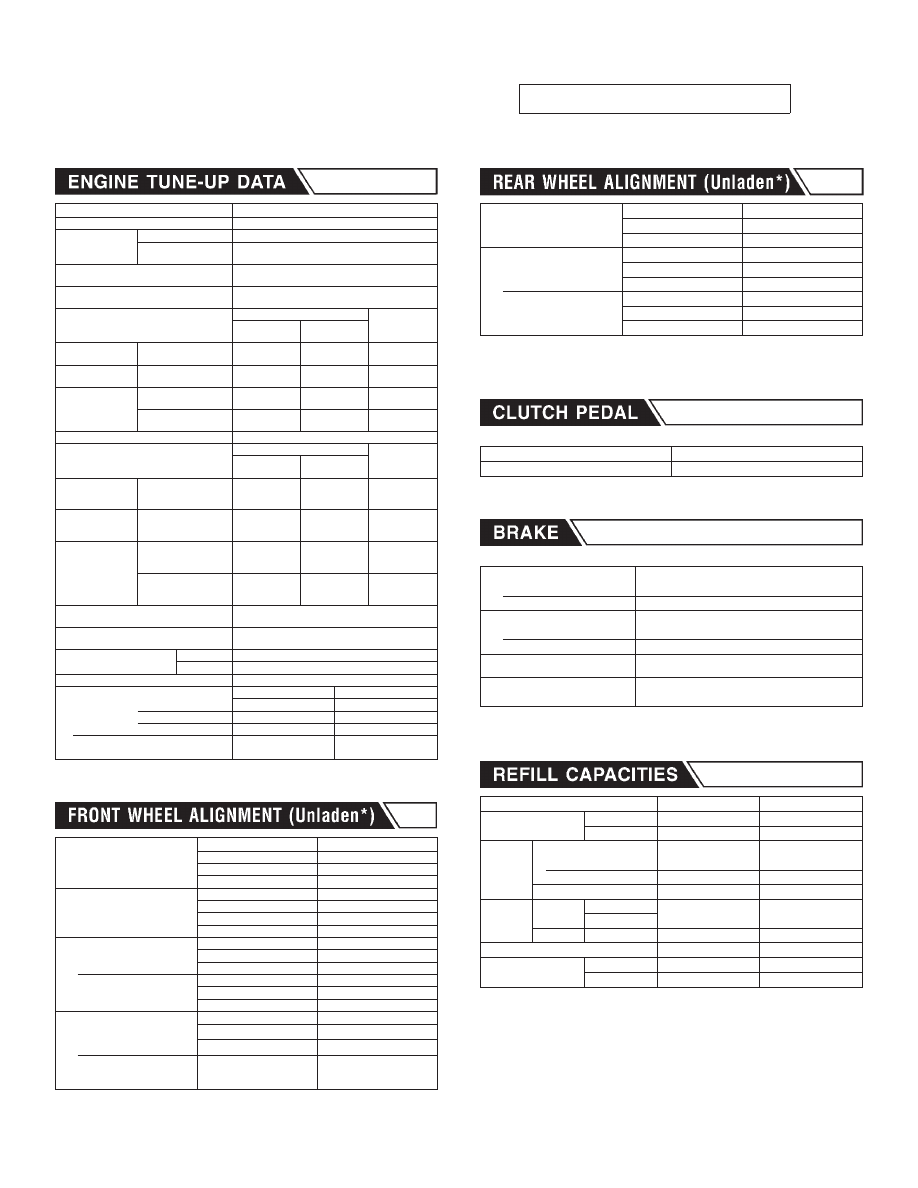
2002

Engine model

SR20DE

Firing order

1-3-4-2

Idle speed

rpm

M/T

800±50

A/T
(in “N” position)

800±50

Ignition timing

(degree BTDC at idle speed)

M/T:

15°±2°

A/T:

CO% at idle

Idle mixture screw is preset and

sealed at factory.

Drive belt deflection adjustment (Cold)

mm (in)

Used belt

New belt

Limit

After

adjustment

Compressor

With air conditioner
compressor

9 (0.35)

5.5 - 6.5

(0.217 - 0.256)

4.5 - 5.5

(0.177 - 0.217)

Generator

Without air condi-
tioner compressor

12 - 13

(0.47 - 0.51)

8 - 9

(0.31 - 0.35)

7 - 8

(0.28 - 0.31)

Power steering oil
pump

With air conditioner
compressor

12 (0.47)

8 - 9

(0.31 - 0.35)

7 - 8

(0.28 - 0.31)

Without air condi-
tioner compressor

12 (0.47)

8 - 9

(0.31 - 0.35)

7 - 8

(0.28 - 0.31)

Applied pushing force

98 N (10 kg, 22 lb)

Drive belt tension adjustment (Cold)

N (kg, lb)

Used belt

New belt

Limit

After

adjustment

Compressor

With air conditioner
compressor

304 (31, 68)

534 - 623

(54.5 - 63.5,

120.2 - 140.0)

652 - 740

(66.5 - 75.5,

146.6 - 166.5)

Generator

Without air condi-
tioner compressor

264 (26.9, 59.3)

493 - 583

(50.3 - 59.5,

110.9 - 131.2)

603 - 691

(61.5 - 70.5,

135.6 - 155.5)

Power steering oil
pump

With air conditioner
compressor

264 (26.9, 59.3)

495 - 583

(50.5 - 59.5,

111.4 - 131.2)

603 - 691

(61.5 - 70.5,

135.6 - 155.5)

Without air condi-
tioner compressor

264 (26.9, 59.3)

493 - 583

(50.3 - 59.5,

110.9 - 131.2)

603 - 691

(61.5 - 70.5,

135.6 - 155.5)

Radiator cap relief pressure

kPa (kg/cm

2

, psi)

78 - 98 (0.8 - 1.0, 11 - 14)

Cooling system leakage testing pressure

kPa (kg/cm

2

, psi)

157 (1.6, 23)

Compression pressure

kPa (kg/cm

2

, psi)/rpm

Standard

1,275 (13.0, 185)/300

Minimum

1,079 (11.0, 156)/300

High tension cable resistance

13.6 - 18.4 k

/m (4.15 - 5.61 k

/ft) at 25°C (77°F)

Spark plug

Platinum tipped type

Conventional type

Type

Standard

PFR5G-11

BKR5E

Hot

Cold

PFR6G-11, PFR7G-11

BKR6E, BKR7E

Gap

mm (in)

Nominal 1.1 (0.043)

0.8 - 0.9

(0.031 - 0.035)

Camber

Degree minute

(Decimal degree)

Minimum

−0°45

(−0.75°)

Nominal

0° (0°)

Maximum

0°45

(0.75°)

Left and right difference

45

(0.75°) or less

Caster

Degree minute

(Decimal degree)

Minimum

1°10

(1.17°)

Nominal

1°55

(1.92°)

Maximum

2°40

(2.67°)

Left and right difference

45

(0.75°) or less

Total toe-in

Minimum

0 (0)

Distance (A − B)

mm (in)

Nominal

1 (0.04)

Maximum

2 (0.08)

Angle (left plus right)

Degree minute

(Decimal degree)

Minimum

0

(0.00°)

Nominal

6

(0.10°)

Maximum

12

(0.20°)

Wheel turning angle (Full turn)

Minimum

31°00

(31.00°)

Inside

Degree minute

(Decimal degree)

Nominal

34°00

(34.00°)

Maximum

35°00

(35.00°)

Outside

Degree minute

(Decimal degree)

Nominal

29°00

(29.00°)

* Fuel, radiator coolant and engine oil full.

Spare tire, jack, hand tools and mats in designated positions.

Camber

Degree minute

(Decimal degree)

Minimum

−2°03

(−2.05°)

Nominal

−1°18

(−1.30°)

Maximum

−0°33

(−0.55°)

Total toe-in

Minimum

0 (0)

Distance (A − B)

mm (in)

Nominal

4 (0.16)

Maximum

8 (0.31)

Angle (left plus right)

Degree minute

(Decimal degree)

Minimum

0 (0.00°)

Nominal

24

(0.40°)

Maximum

48

(0.80°)

* Fuel, radiator coolant and engine oil full.

Spare tire, jack, hand tools and mats in designated positions.

Unit: mm (in)

Pedal height

158 - 168 (6.22 - 6.61)

Pedal free play

9 - 16 (0.35 - 0.63)

Unit: mm (in)

Front brake

Pad wear limit

2.0 (0.079)

Rotor repair limit

20.0 (0.787)

Rear brake

Pad wear limit

1.5 (0.059)

Rotor repair limit

8.0 (0.315)

Pedal free height

M/T: 151 - 161 (5.94 - 6.34)

A/T: 159 - 169 (6.26 - 6.65)

Parking brake

Number of notches*1

6 - 7

*1 At pulling force: 196 N (20 kg, 44 lb)

Unit

Liter

US measure

Coolant with reservoir

M/T

6.2

6-1/2 qt

A/T

6.2

6-1/2 qt

Engine*

Drain and refill

With oil filter

3.3

3-1/2 qt

Without oil filter

3.1

3-1/4 qt

Dry engine (engine overhaul)

4.0

4-1/4 qt

Transaxle

M/T

RS5F70A

3.0

5-1/4 pt

RS5F70V

A/T

RE4F03B/W

7.0

7-3/8 qt

Power steering system

0.9

1 qt

Air conditioning sys-
tem

Refrigerant

0.55 - 0.65 kg

1.21 - 1.43 lb

Compressor oil

0.2

0.68 fl oz

* For further details, see “Changing Engine Oil” in MA section.

EDITION: NOVEMBER 2000
REVISION: DECEMBER 2001

QUICK REFERENCE INDEX

INCH TO METRIC CONVERSION TABLE

(Rounded-off for automotive use)

inches

mm

inches

mm

.100

2.54

.610

15.49

.110

2.79

.620

15.75

.120

3.05

.630

16.00

.130

3.30

.640

16.26

.140

3.56

.650

16.51

.150

3.81

.660

16.76

.160

4.06

.670

17.02

.170

4.32

.680

17.27

.180

4.57

.690

17.53

.190

4.83

.700

17.78

.200

5.08

.710

18.03

.210

5.33

.720

18.29

.220

5.59

.730

18.54

.230

5.84

.740

18.80

.240

6.10

.750

19.05

.250

6.35

.760

19.30

.260

6.60

.770

19.56

.270

6.86

.780

19.81

.280

7.11

.790

20.07

.290

7.37

.800

20.32

.300

7.62

.810

20.57

.310

7.87

.820

20.83

.320

8.13

.830

21.08

.330

8.38

.840

21.34

.340

8.64

.850

21.59

.350

8.89

.860

21.84

.360

9.14

.870

22.10

.370

9.40

.880

22.35

.380

9.65

.890

22.61

.390

9.91

.900

22.86

.400

10.16

.910

23.11

.410

10.41

.920

23.37

.420

10.67

.930

23.62

.430

10.92

.940

23.88

.440

11.18

.950

24.13

.450

11.43

.960

24.38

.460

11.68

.970

24.64

.470

11.94

.980

24.89

.480

12.19

.990

25.15

.490

12.45

1.000

25.40

.500

12.70

2.000

50.80

.510

12.95

3.000

76.20

.520

13.21

4.000

101.60

.530

13.46

5.000

127.00

.540

13.72

6.000

152.40

.550

13.97

7.000

177.80

.560

14.22

8.000

203.20

.570

14.48

9.000

228.60

.580

14.73

10.000

254.00

.590

14.99

20.000

508.00

.600

15.24

METRIC TO INCH CONVERSION TABLE

(Rounded-off for automotive use)

mm

inches

mm

inches

1

.0394

51

2.008

2

.079

52

2.047

3

.118

53

2.087

4

.157

54

2.126

5

.197

55

2.165

6

.236

56

2.205

7

.276

57

2.244

8

.315

58

2.283

9

.354

59

2.323

10

.394

60

2.362

11

.433

61

2.402

12

.472

62

2.441

13

.512

63

2.480

14

.551

64

2.520

15

.591

65

2.559

16

.630

66

2.598

17

.669

67

2.638

18

.709

68

2.677

19

.748

69

2.717

20

.787

70

2.756

21

.827

71

2.795

22

.866

72

2.835

23

.906

73

2.874

24

.945

74

2.913

25

.984

75

2.953

26

1.024

76

2.992

27

1.063

77

3.031

28

1.102

78

3.071

29

1.142

79

3.110

30

1.181

80

3.150

31

1.220

81

3.189

32

1.260

82

3.228

33

1.299

83

3.268

34

1.339

84

3.307

35

1.378

85

3.346

36

1.417

86

3.386

37

1.457

87

3.425

38

1.496

88

3.465

39

1.535

89

3.504

40

1.575

90

3.543

41

1.614

91

3.583

42

1.654

92

3.622

43

1.693

93

3.661

44

1.732

94

3.701

45

1.772

95

3.740

46

1.811

96

3.780

47

1.850

97

3.819

48

1.890

98

3.858

49

1.929

99

3.898

50

1.969

100

3.937


Attachment No.11

TID

CID

P0420

01H

01H

Max.

 X

-

P0420

02H

81H

Min.

 X

-

P0440

05H

03H

Max.

 X

-

P1440

05H

03H

Max.

 X

-

EVAP control system purge flow monitoring

P1447

06H

83H

Min.

 X

mV

P0133

09H

04H

Max.

 X

ms

P0131

0AH

84H

Min.

 X

mV

P0130

0BH

04H

Max.

 X

mV

P0132

0CH

04H

Max.

 X

mV

P0134

0DH

04H

Max.

 X

s

P0139

19H

86H

Min.

 X

mV/500ms

P0137

1AH

86H

Min.

 X

mV

P0140

1BH

06H

Max.

 X

mV

P0138

1CH

06H

Max.

 X

mV

P0135

29H

08H

Max.

 X

mV

P0135

2AH

88H

Min.

 X

mV

P0141

2DH

0AH

Max.

 X

mV

P0141

2EH

8AH

Min.

 X

mV

P0400

31H

8CH

Min.

 X

P0400

32H

8CH

Min.

 X

P0400

33H

8CH

Min.

 X

P0400

34H

8CH

Min.

 X

P1402

35H

0CH

Max.

 X

TEST VALUE AND TEST LIMIT (GST ONLY — NOT APPLICABLE TO CONSULT-II)

The following is the information specified in Mode 6 of SAE J1979.

The test value is a parameter used to determine whether a system/circuit diagnostic test is “OK” or “NG” while
being monitored by the ECM during self-diagnosis. The test limit is a reference value which is specified as the
maximum or minimum value and is compared with the test value being monitored.
Items for which these data (test value and test limit) are displayed are the same as SRT code items.

These data (test value and test limit) are specified by Test ID (TID) and Component ID (CID) and can be dis-
played on the GST screen.

: Applicable ・: Not applicable

SRT item 

Self-diagnostic test item

DTC

Test value

 (GST display) Te s t limit  Application

Unit

CATALYST

Three way catalyst function 

EVAP SYSTEM

EVAP control system (Small leak)

HO2S

Heated oxygen sensor 1

Heated oxygen sensor 2

HO2S HTR

Heated oxygen sensor 1 heater

Heated oxygen sensor 2 heater

EGR SYSTEM

EGR function


Content   ..  401  402  403  404   ..