Infiniti G20 (P11). Manual - part 391


  Index      Infiniti     Infiniti G20 (P11) - service repair manual 1999-2002 year


Search            


Content   ..  389  390  391  392   ..


Infiniti G20 (P11). Manual - part 391


SEM593G

SEM381F

I

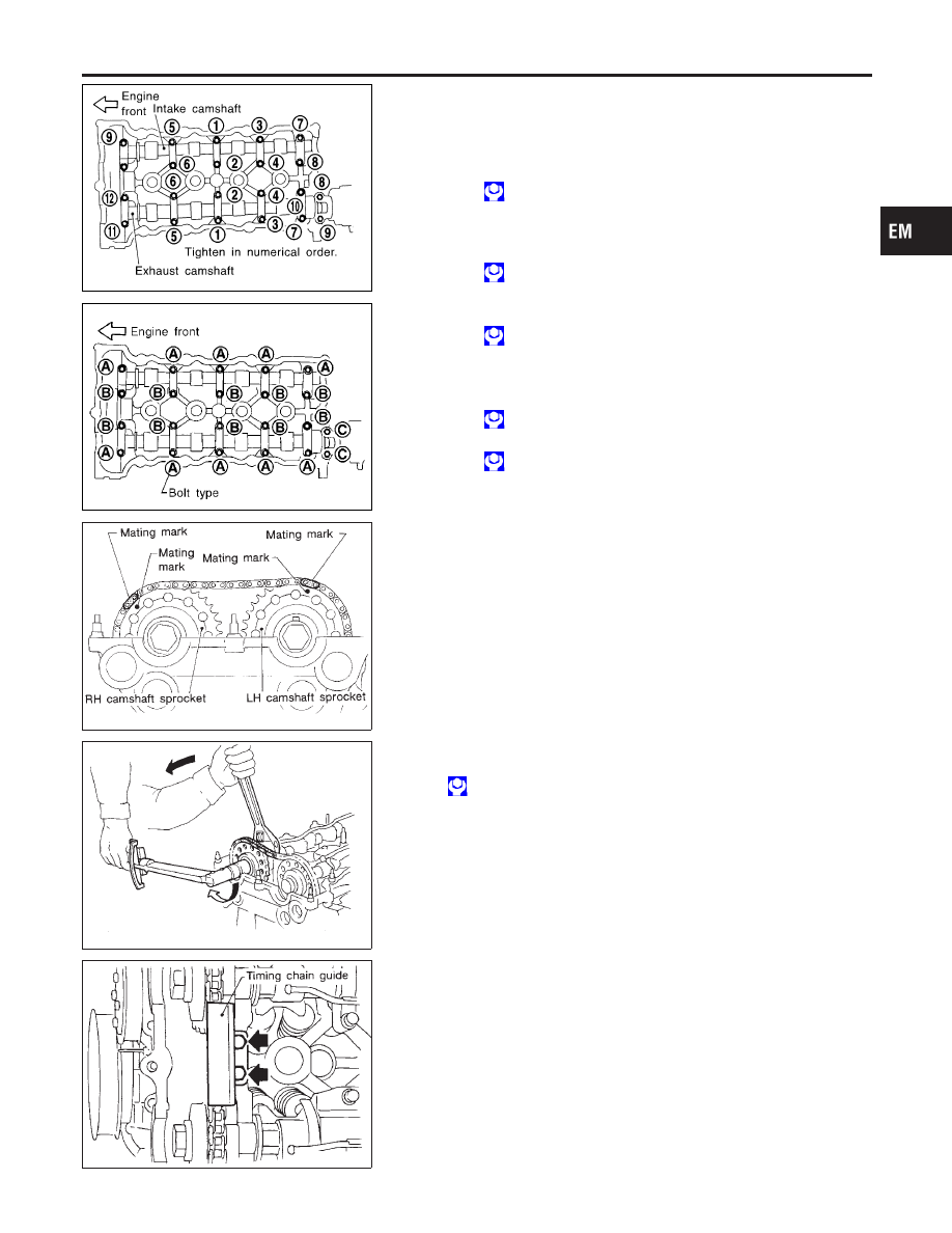
Tightening procedure

STEP 1:

Intake camshaft

Tighten bolts 9 - 10 in that order then tighten bolts
1 - 8 in numerical order.

: 2 N·m (0.2 kg-m, 1.4 ft-lb)

Exhaust camshaft

Tighten bolts 11 - 12 in that order then tighten
bolts 1 - 10 in numerical order.

: 2 N·m (0.2 kg-m, 1.4 ft-lb)

STEP 2:

Tighten bolts in the specified order.

: 6 N·m (0.6 kg-m, 4.3 ft-lb)

STEP 3:

Tighten bolts in the specified order.

Bolt type A B

: 10 - 12 N·m (1.0 - 1.2 kg-m, 7.2 - 8.7 ft-lb)

Bolt type C

: 18 - 25 N·m (1.8 - 2.6 kg-m, 13 - 19 ft-lb)

SEM696DA

11. Install camshaft sprockets.

Line up mating marks on timing chain with mating marks
on camshaft sprockets.

SEM584D

I

Lock camshafts as shown in figure and tighten to specified
torque.

: 137 - 157 N·m (14.0 - 16.0 kg-m, 101 - 116 ft-lb)

Apply engine oil to threads and seating surfaces of cam-
shaft sprocket bolts before installing them.

SEM071D

12. Install timing chain guide.

GI

MA

LC

EC

FE

CL

MT

AT

AX

SU

BR

ST

RS

BT

HA

SC

EL

IDX

CYLINDER HEAD

Installation (Cont’d)

EM-49

SEM227D

13. Install distributor.

I

Make sure that position of camshaft is as shown in figure.

SEM594G

I

Make sure that No. 1 piston is set at TDC and that distribu-
tor is set at No. 1 cylinder spark position.

SEM990C

14. Install chain tensioner.

I

Make sure the camshaft sprockets are tightened com-
pletely.
Press cam stopper down and “press-in” sleeve until hook
can be engaged on pin. When tensioner is bolted in posi-
tion the hook will release automatically.

SEM991C

I

Make sure arrow “A” points toward engine front.

SEM580D

15. Install oil filter bracket (SR20DE engine only) and power steer-

ing oil pump bracket.

16. Install intake manifold supports.

CYLINDER HEAD

Installation (Cont’d)

EM-50

SEM366D

SEM595G

17. Remove all old liquid gasket from mating surfaces of rocker

cover and cylinder head.

18. Apply a continuous bead of liquid gasket to mating surfaces of

rocker cover gasket and cylinder head.

I

Use Genuine Liquid Gasket or equivalent.

SEM596G

19. Install rocker cover.
1)

Tighten bolts 1 - 10 - 11 - 13 - 8 in that order to 8 to 10 N·m
(0.8 to 1.0 kg-m, 69 to 89 in-lb).

2)

Tighten bolts 1 through 13 in numerical order to 8 to 10
N·m (0.8 to 1.0 kg-m, 70 to 89 in-lb).

20. Refit spark plugs and leads.
21. Install vacuum hoses, fuel hoses, wires, harness, connectors

and so on.

22. Install power steering oil pump and alternator.
23. Install water pump pulley and drive belts.
24. Install intake manifold collector and brackets.
25. Refit air duct to intake manifold.
26. Install radiator.
27. Refit hoses and refill with coolant. (Refer to MA-15.)
28. Install engine side cover and front RH wheel.
29. Install engine under covers.

GI

MA

LC

EC

FE

CL

MT

AT

AX

SU

BR

ST

RS

BT

HA

SC

EL

IDX

CYLINDER HEAD

Installation (Cont’d)

EM-51

Removal and Installation

NCEM0022

SEM518F

1.

Stopper

2.

Bracket

3.

Front insulator assembly

4.

Center member

5.

Pad

6.

Right insulator assembly

7.

Exhaust bracket

8.

Bracket

9.

Rear insulator assembly

10. Left insulator assembly (A/T)

WARNING:

I

Position vehicle on a flat and solid surface.

I

Place chocks at front and back of rear wheels.

I

Do not remove engine until exhaust system has com-
pletely cooled off, otherwise you may burn yourself and/or
fire may break out in fuel line.

I

Before disconnecting fuel hose, release pressure. Refer to
EC-50, 
“Fuel Pressure Release”.

I

Before removing front axle from transaxle, place safety
stands under designated front supporting points. Refer to
GI-46, 
“Garage Jack and Safety Stand”.

I

Be sure to lift engine and transaxle in a safe manner.

I

For engines not equipped with engine slingers, attach
proper slingers and bolts described in PARTS CATALOG.

CAUTION:

I

When lifting engine, be sure to clear surrounding parts.
Use special care near accelerator wire casing, brake lines
and brake master cylinder.

ENGINE ASSEMBLY

Removal and Installation

EM-52


Content   ..  389  390  391  392   ..