Infiniti G20 (P11). Manual - part 389
AEM343
Use a depth gauge to measure the distance between the mount-
ing surface of the cylinder head spring seat and the valve stem end.
If the distance is shorter than the specified valve, repeat step 5
above to adjust it.
If it is longer, replace the valve seat with a new one.
Valve seat resurface limit:
42.74 - 43.26 mm (1.6827 - 1.7031 in)
SEM188A
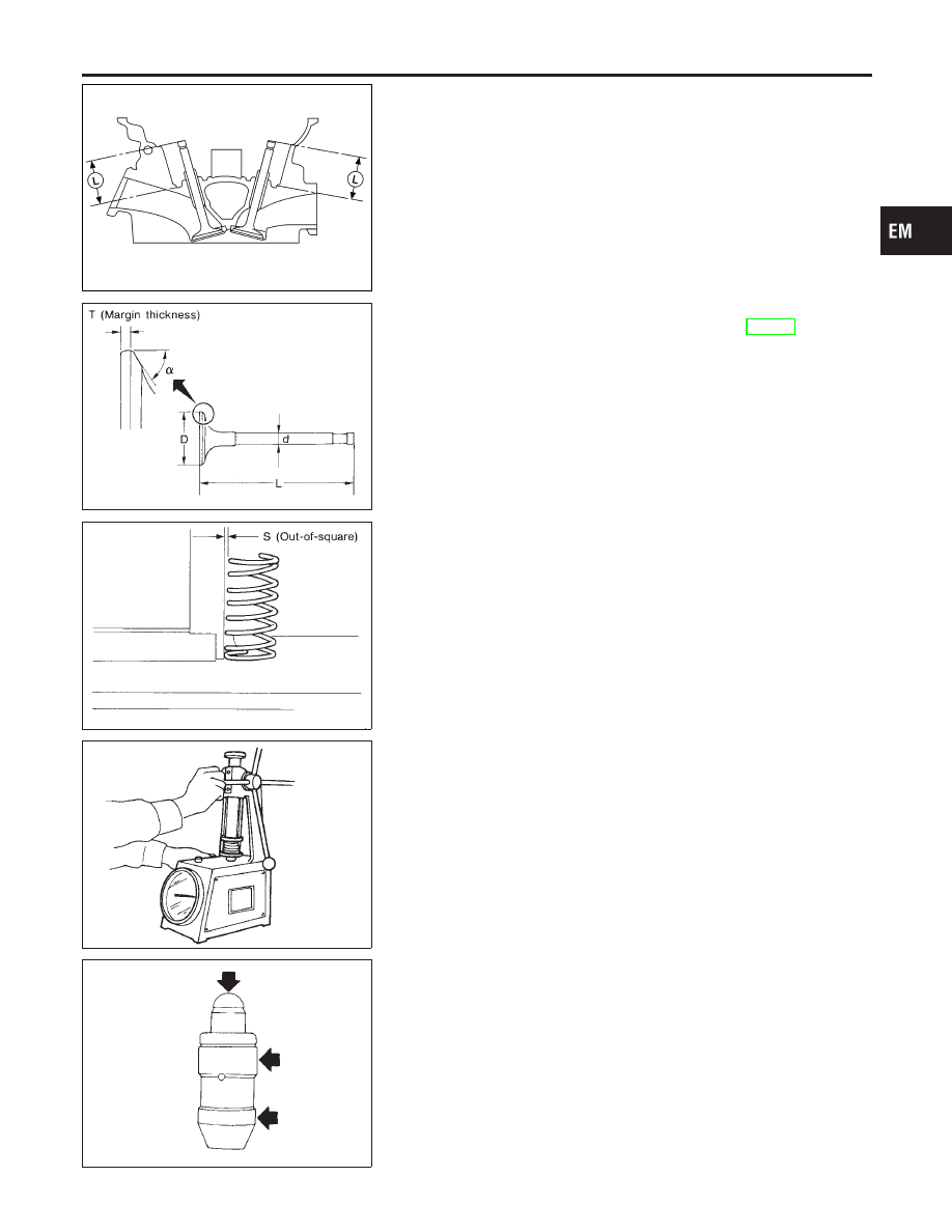
VALVE DIMENSIONS
NCEM0019S12
Check dimensions of each valve. Refer to SDS, EM-69.
When valve head has been worn down to 0.5 mm (0.020 in) in
margin thickness, replace valve.
Grinding allowance for valve stem tip is 0.2 mm (0.008 in) or
less.
SEM288A
VALVE SPRING
NCEM0019S13
Squareness
NCEM0019S1301
1.
Measure dimension “S”.
Out-of-square “S”:
Less than 2.1 mm (0.083 in)
2.
If it exceeds the limit, replace spring.
EM113
Pressure
NCEM0019S1302
Check valve spring pressure at specified spring height.
Pressure:
Standard
519 - 571 N (52.9 - 58.2 kg, 116.7 - 128.4 lb) at 27.0
mm (1.063 in)
Limit
More than 491.8 N (50.16 kg, 110.56 lb) at 27.0 mm
(1.063 in)
If it exceeds the limit, replace spring.
SEM935C
HYDRAULIC LASH ADJUSTER
NCEM0019S14
1.
Check contact and sliding surfaces for wear or score.
GI
MA
LC
EC
FE
CL
MT
AT
AX
SU
BR
ST
RS
BT
HA
SC
EL
IDX
CYLINDER HEAD
Inspection (Cont’d)
EM-41