Infiniti G20 (P11). Manual - part 388
SEM927C
CAMSHAFT JOURNAL CLEARANCE
1.
Install camshaft bracket and tighten bolts. Refer to EM-23.
2.
Measure inner diameter of camshaft bearing.
Standard inner diameter:
28.000 - 28.021 mm (1.1024 - 1.1032 in)
SEM012A
3.
Measure outer diameter of camshaft journal.
Standard outer diameter:
27.935 - 27.955 mm (1.0998 - 1.1006 in)
4.
Calculate camshaft journal clearance.
Camshaft journal clearance = standard inner diameter
− standard outer diameter:
Standard
0.030 - 0.071 mm (0.0012 - 0.0028 in)
Limit
0.15 mm (0.0059 in)
5.
If clearance exceeds the limit, replace camshaft and remea-
sure camshaft journal clearance.
I
If clearance still exceeds the limit after replacing camshaft,
replace cylinder head.
SEM062G
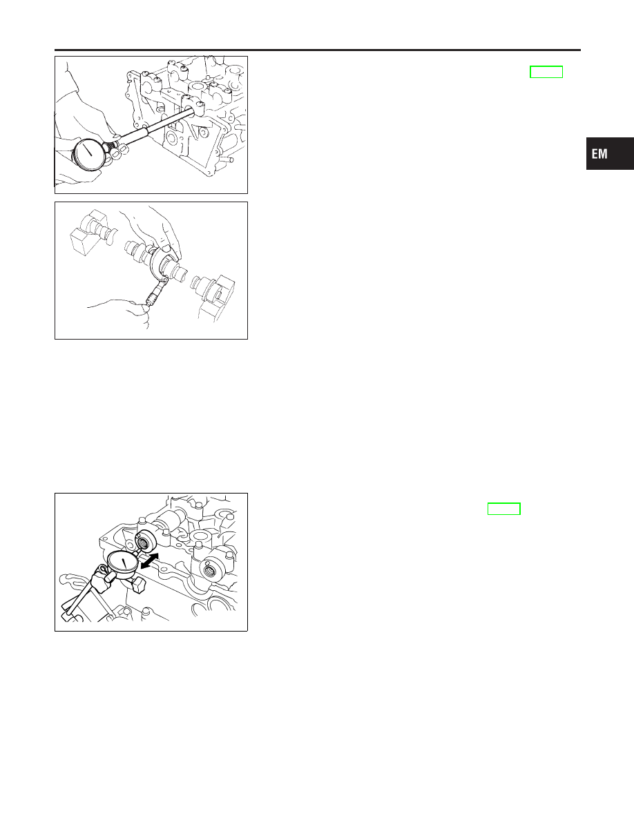
CAMSHAFT END PLAY
NCEM0019S06
1.
Install camshaft in cylinder head. Refer to EM-23.
2.
Measure camshaft end play.
Camshaft end play:
Standard
0.055 - 0.139 mm (0.0022 - 0.0055 in)
Limit
0.20 mm (0.0079 in)
3.
If end play exceeds the limit, replace camshaft and remeasure
camshaft end play.
I
If end play still exceeds the limit after replacing camshaft,
replace cylinder head.
GI
MA
LC
EC
FE
CL
MT
AT
AX
SU
BR
ST
RS
BT
HA
SC
EL
IDX
CYLINDER HEAD
Inspection (Cont’d)
EM-37