Infiniti G20 (P11). Manual - part 383
BEM008
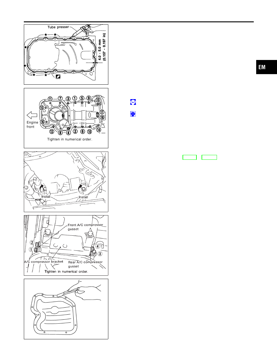
I
For areas marked with “
★
”, apply liquid gasket around the
outer side of the bolt hole as shown.
I
Be sure liquid gasket diameter is 4.0 to 5.0 mm (0.157 to
0.197 in).
I
Attaching should be done within 5 minutes after coating.
SEM025G
c.
Tighten nuts and bolts in numerical order.
Bolts 1 - 16:
: 16 - 19 N·m (1.6 - 1.9 kg-m, 12 - 14 ft-lb)
Bolts 17, 18:
: 6.4 - 7.5 N·m (0.65 - 0.76 kg-m, 56.4 - 66.0 in-lb)
SEM224D
2.
Install the two engine-to-transaxle bolts.
For tightening torque, refer to MT-12 or AT-283, “REMOVALAND
INSTALLATION”.
3.
Install rear cover plate.
AEM235
4.
Install A/C compressor gussets.
5.
Install A/T control cable. (A/T only)
6.
Install center member.
7.
Install front exhaust tube.
8.
Install baffle plate.
SEM026G
9.
Install steel oil pan.
a.
Use a scraper to remove old liquid gasket from mating surface
of steel oil pan.
I
Also remove old liquid gasket from mating surface of alu-
minum oil pan.
GI
MA
LC
EC
FE
CL
MT
AT
AX
SU
BR
ST
RS
BT
HA
SC
EL
IDX
OIL PAN
Installation (Cont’d)
EM-17