Infiniti G20 (P11). Manual - part 357
HAZARD REMINDER CHECK
=NCEL0115S08
1
CHECK HAZARD INDICATOR
Check if hazard indicator flashes with hazard switch.
Does hazard indicator operate?
Yes
©
GO TO 2.
No
©
Check “hazard indicator” circuit.
2
CHECK HAZARD REMINDER OPERATION
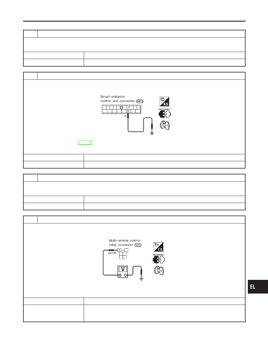
1. Disconnect smart entrance control unit connector.
2. Apply ground to control unit terminal 7.
SEL890V
Refer to wiring diagram in EL-195.
Does hazard indicator illuminate?
Yes
©
Replace smart entrance control unit.
No
©
GO TO 3.
3
CHECK MULTI-REMOTE CONTROL RELAY
Check multi-remote control relay.
OK or NG
OK
©
GO TO 4.
NG
©
Replace.
4
CHECK POWER SUPPLY FOR MULTI-REMOTE CONTROL RELAY
1. Disconnect multi-remote control relay connector.
2. Check voltage between terminal 1 and ground.
SEL244VB
Battery voltage should exist.
OK or NG
OK
©
GO TO 5.
NG
©
Check the following.
I
10A fuse [No. 20, located in fuse block (J/B)]
I
Harness for open or short between multi-remote control relay and fuse
GI
MA
EM
LC
EC
FE
CL
MT
AT
AX
SU
BR
ST
RS
BT
HA
SC
IDX
MULTI-REMOTE CONTROL SYSTEM
Trouble Diagnoses (Cont’d)
EL-205