Infiniti G20 (P11). Manual - part 349
Trouble Diagnoses
NCEL0105
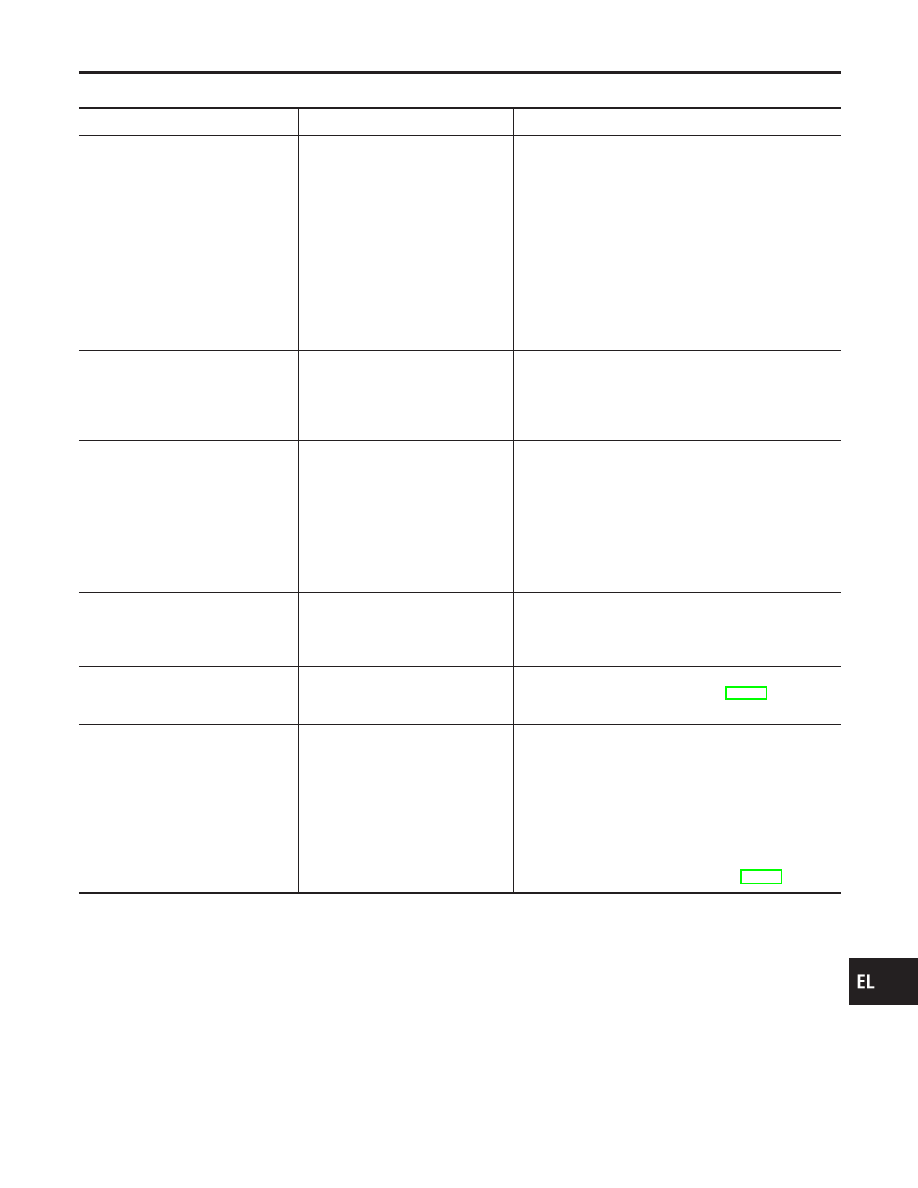
Symptom
Possible cause
Repair order
None of the power windows can be
operated using any switch.
1. 10A fuse, 30A fusible link and
M13 circuit breaker
2. Power window main switch
ground circuit
3. Power window relay ground cir-
cuit
4. Power window relay
5. Open/short in power window
main switch circuit
6. Power window main switch
1. Check 10A fuse [No. 8, located in fuse block (J/B)],
30A fusible link (letter d, located in fuse and fusible
link box) and M13 circuit breaker. Turn ignition
switch “ON” and verify battery positive voltage is
present at terminals 1 and 3 of power window relay
and terminal 7 of power window main switch.
2. Check power window main switch ground circuit.
3. Check power window relay ground circuit.
4. Check power window relay.
5. Check the wire between power window relay termi-
nal 5 and power window main switch terminal 11
for open/short circuit.
6. Check power window main switch.
Driver side power window cannot
be operated but other windows can
be operated.
1. Driver side power window regu-
lator circuit
2. Driver side power window regu-
lator
3. Power window main switch
1. Check harness between power window main switch
and power window regulator for open or short cir-
cuit.
2. Check driver side power window regulator.
3. Check power window main switch.
Passenger power window cannot
be operated.
1. Power window switches
2. Passenger side power window
regulators
3. Power window main switch
4. Power window circuit
1. Check power window switch.
2. Check passenger side power window regulator.
3. Check power window main switch.
4. Check the following.
a. Check harnesses between power window main
switch and power window switch for open/short cir-
cuit.
b. Check harnesses between power window switch
and power window regulator for open/short circuit.
Passenger power window cannot
be operated using power window
main switch but can be operated by
power window switch.
1. Power window main switch
1. Check power window main switch.
Driver side power window auto-
matic operation does not function
properly.
1. Power window main switch
2. Encoder and limit switch
1. Check power window main switch.
2. Check encoder and limit switch. (EL-174)
Retained power operation does not
operate properly.
1. RAP signal circuit
2. Driver or passenger side door
switch circuit
3. Smart entrance control unit
1. Check harness between power window relay termi-
nal 1 and smart entrance control unit terminal 5 for
open or short circuit.
2. Check the following:
a. Harness between smart entrance control unit and
driver or passenger side door switch for open or
short circuit
b. Driver or passenger side door switch ground circuit
c. Driver or passenger side door switch.
3. Check smart entrance control unit. (EL-246)
GI
MA
EM
LC
EC
FE
CL
MT
AT
AX
SU
BR
ST
RS
BT
HA
SC
IDX
POWER WINDOW
Trouble Diagnoses
EL-173